Telescopic gun sight free of parallax error

a technology of parallax error and telescopic gun, applied in the field of optical sights, can solve the problems of difficult human eye, if not impossible, and do not completely eliminate the requirement, and achieve the effect of eliminating parallax error, simple and inexpensively, and easy implementation

Active Publication Date: 2011-11-10
LUCIDA RES
View PDF15 Cites 15 Cited by
  • Summary
  • Abstract
  • Description
  • Claims
  • Application Information

AI Technical Summary

Benefits of technology

[0014]The present invention teaches a parallax-free telescopic sight with a wide viewing angle. It overcomes all the limitations of the prior art by eliminating parallax error at all distances with no need for user adjustments. Furthermore, the present invention achieves these improvements simply and inexpensively with an easily implemented coherent image conduit.
[0015]In accordance with one embodiment, this invention introduces a telescopic gun sight comprising an objective lens, an image erecting means, and a fiber optic faceplate, whose apparent point of aim is insensitive to both the lateral and longitudinal location of the shooter's eye, thereby providing a wide, comfortable viewing angle and eliminating parallax error.

Problems solved by technology

It is very difficult for the human eye, if not impossible, to try to switch its focus from a rear sight to a front sight to a target as required with metallic sights, and its frustrating to say the least.
Current designs, however, do not completely eliminate the requirement that the shooter must align his eye with the sight.
A first disadvantage of current telescopic sights is that if the shooter's eye is not aligned with the optical axis of the sight, he will not see the complete field of view.
This problem becomes more prominent in high-magnification scopes where even a slight miss-alignment of the eye from the optical axis can cause the target image to partially or completely black out.
In high stress situations, this makes fast target acquisition very difficult.
A second, more sever, disadvantage of telescopic sights is that the shooter might also misplace the shot due to a phenomenon called parallax error.
Parallax error is a serious issue as it prevents a shooter from aiming accurately if he happens to be looking at an angle into the sight.
However, if the target is at any distance greater than or less than 100 yards, which is often the case, there is potential for misplacing the shot as the parallax error may cause the shooter to aim at an offset distance from the intended target point.
A major drawback with AO scopes is that to adjust the objective for parallax-free aiming, the shooter must either know the exact distance to the target or use a process of trial and error.
If the reticle moves around on the target, the shooter is seeing parallax error.
Clearly, this is a time consuming and often impractical task to do in the field.
This may help detect parallax error but it doesn't actually eliminate it.
Therefore, this design is not a solution to the problem.

Method used


Image

  • Telescopic gun sight free of parallax error
  • Telescopic gun sight free of parallax error
  • Telescopic gun sight free of parallax error

Examples


first embodiment

A. First Embodiment of the Invention

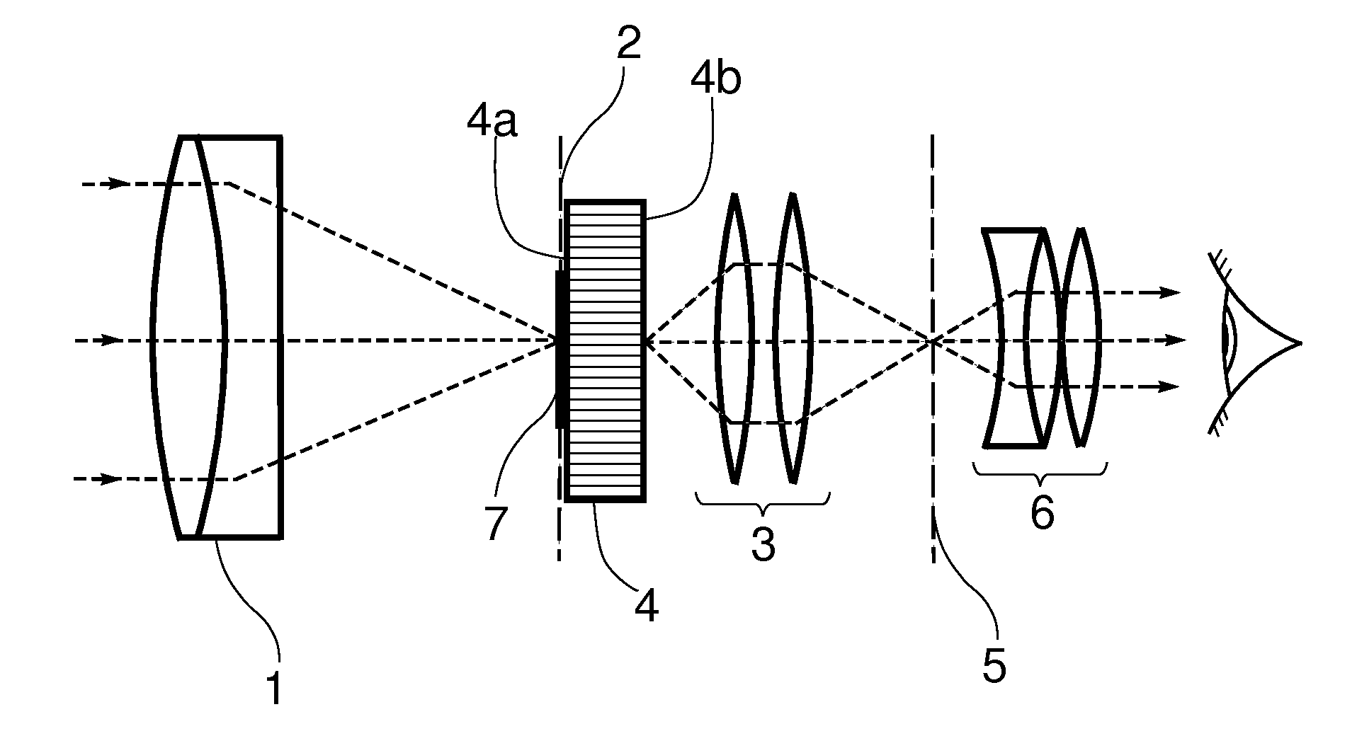
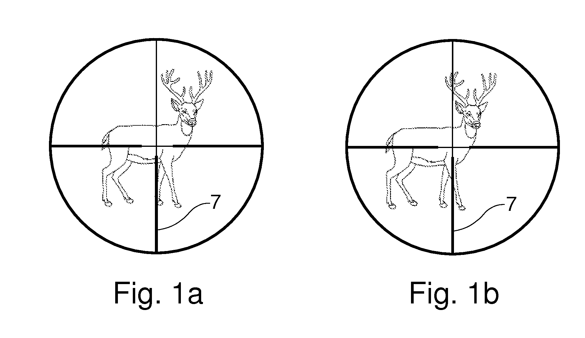
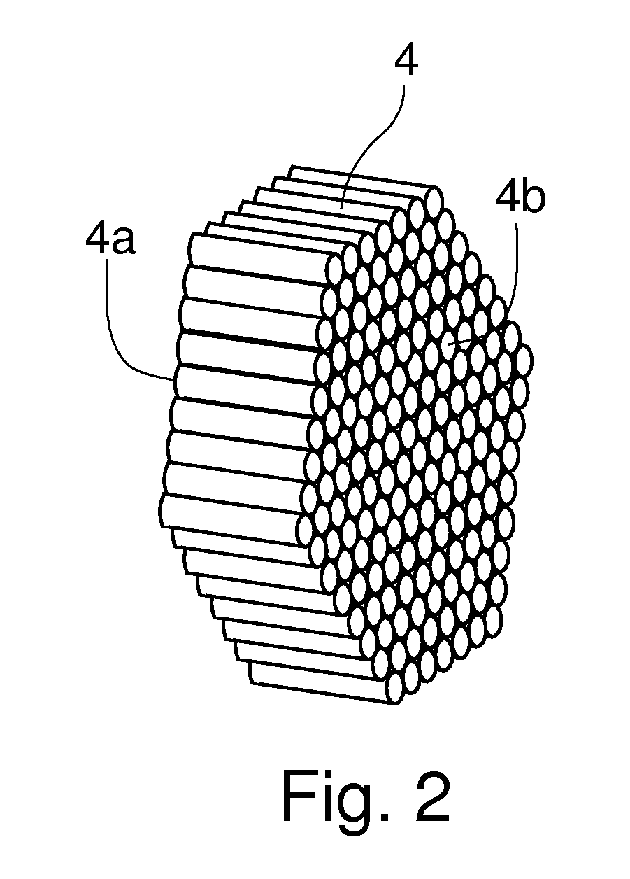
[0029]FIG. 3 shows a side schematic view of a telescopic gun sight in accordance with a first embodiment of the invention. With reference to FIG. 3, the first embodiment of the invention has an objective 1 which is an image forming device. The objective 1 has a focal plane 2 and an optical axis (not shown). The optical axis of the objective forms the optical axis of the telescopic gun sight. An image erecting means 3 is positioned on the optical axis after the objective. A fiber optic faceplate 4 is placed on the optical axis after the image erecting means 3. A reticle 7 is placed on the optical axis coplanar with the objective focal plane 2 to designate the point of aim. The entire assembly may be encased in a suitable housing. The housing is not an essential feature of the invention and is not shown.

[0030]When said telescopic gun sight is pointed at a distant target, the objective 1 forms a first image of the target at the objective focal plane ...

second embodiment

B. Second Embodiment of the Invention

[0035]FIG. 4 shows a side schematic view of a second embodiment of the invention. In this embodiment an eyepiece 6 is added to the assembly described in the first embodiment. The eyepiece 6 is positioned on the sight's optical axis, after the fiber optic faceplate 4, and at the rear end of the sight. The eyepiece 6 is positioned such that it converts the target image displayed on the emitting surface 4b of the fiber optic faceplate 4 into a virtual (and possibly magnified) image for the shooter's eye to see. The eyepiece 6 may comprise one or more lenses or lens groups. Personas skilled in the art of optical engineering are familiar with the principles of designing an eyepiece. A plurality of suitable eyepiece designs can be found in Handbook of Optical Systems, Vol. 4: Survey of Optical Instruments edited by Herbert Gross, Wiley-VCH Verlag GMBH & Co., Weinheim, Germany, 2008, ISBN 978-3-527-40380-6.

[0036]The added eyepiece 6 allows the shooter t...

third embodiment

C. Third Embodiment of the Invention

[0037]FIG. 5 shows a side schematic view of a third embodiment of the invention. This embodiment is a variation of the second embodiment wherein the fiber optic faceplate is relocated to the objective's focal plane. This can provide certain advantages in terms of the optimal design of optical elements such as objective and eyepiece lenses used in the invention.

[0038]With reference to FIG. 5, the third embodiment of the invention has an objective 1 which is an image forming device. The objective 1 has a focal plane 2 and an optical axis (not shown). The optical axis of the objective forms the optical axis of the telescopic gun sight. A fiber optic faceplate (FOFP) 4 is positioned on the optical axis after the objective such that its incident surface 4a is coplanar with the objective focal plane 2. An image erecting means 3 is positioned on the optical axis after the FOFP 4. An eyepiece 6 is positioned on the optical axis after the image erecting me...


PUM


Abstract

This invention teaches a telescopic gun sight free of parallax error which accurately displays a weapon's point of aim independent of the position of the shooter's eye. Additionally, at least one embodiment of the present invention provides a telescopic sight with a wide viewing angle and a long, comfortable eye-relief.

Description

I. CROSS-REFERENCE TO RELATED APPLICATIONS[0001]Not ApplicableII. FEDERALLY SPONSORED RESEARCH[0002]Not ApplicableIII. SEQUENCE LISTING OR PROGRAM[0003]Not ApplicableIV. FIELD OF THE INVENTION[0004]This application relates to optical sights, specifically to a new means of eliminating parallax error in telescopic gun sights.V. BACKGROUND OF THE INVENTION[0005]A gun sight is a device used to provide an accurate point of aim for firearms such as rifles, handguns and shotguns. Sights are used on other types of weapons such as bows and crossbows as well. Popular gun sights include the traditional metallic sights (also known as “iron sights”) and telescopic sights (also called “rifle scope” or “scope” for short). Other types of sights include red-dot sights, holographic sights, laser sights, etc.[0006]Traditional metallic sights are inexpensive, sturdy and light in weight. However, the shooter is required to line up the rear sight with the front sight and the target. With a telescopic sig...

Claims


Application Information

Patent Timeline
Patent Type & Authority Applications(United States)
IPC IPC(8): F41G1/38
CPCF41G1/38
Inventor JAHROMI, OMID S.
Owner LUCIDA RES
Why Eureka
Try Eureka