Shell And Tube Heat Exchangers

Inactive Publication Date: 2011-11-10
CHEMETICS
View PDF5 Cites 3 Cited by
  • Summary
  • Abstract
  • Description
  • Claims
  • Application Information

AI Technical Summary

Benefits of technology

[0048]An exchanger designed according to the invention may be designed to have the gases alternate sides of the tube wall during the transition between the parallel flow and counter flow sections. Doing so maintains the average shell wall temperature of the exchanger closer to the average tube wall temperature, thus reducing differential thermal growth. Dividing the tubes into two separate sections allows for the differential growth between the shell and tubes to be absorbed in stag

Problems solved by technology

When the shell or tube wall temperature on the corrosive side of the heat exchanger falls below said corrosive vapour's dew point, there is a potential for corrosion.
This can lead to fouling which causes a decrease in performance, an increase in pressure drop, and premature failure of the heat exchanger.
In sulphuric acid manufacturing, both gas streams in a heat exchanger are often potentially corrosive.
This entrained acid mist can rapidly corrode the heat exchanger when it comes into direct contact with the tube walls, especially when said tube walls are directly impacted with droplets of entrained acid mist within the cold inlet gas.
Therefore, these preheat exchangers often experience dew point corrosion issues similar to those in the production of sulphuric acid.
Counter flow exchangers have the highest LMTD of the standard heat exchanger arrangements and therefore require less effective heat transfer area to attain an equivalent heat duty to other heat exchanger designs with equivalent process requirements.
Limiting the heat duty can prevent the minimum tube wall temperature from falling beneath the

Method used


Image

  • Shell And Tube Heat Exchangers
  • Shell And Tube Heat Exchangers
  • Shell And Tube Heat Exchangers

Examples


Embodiment Construction

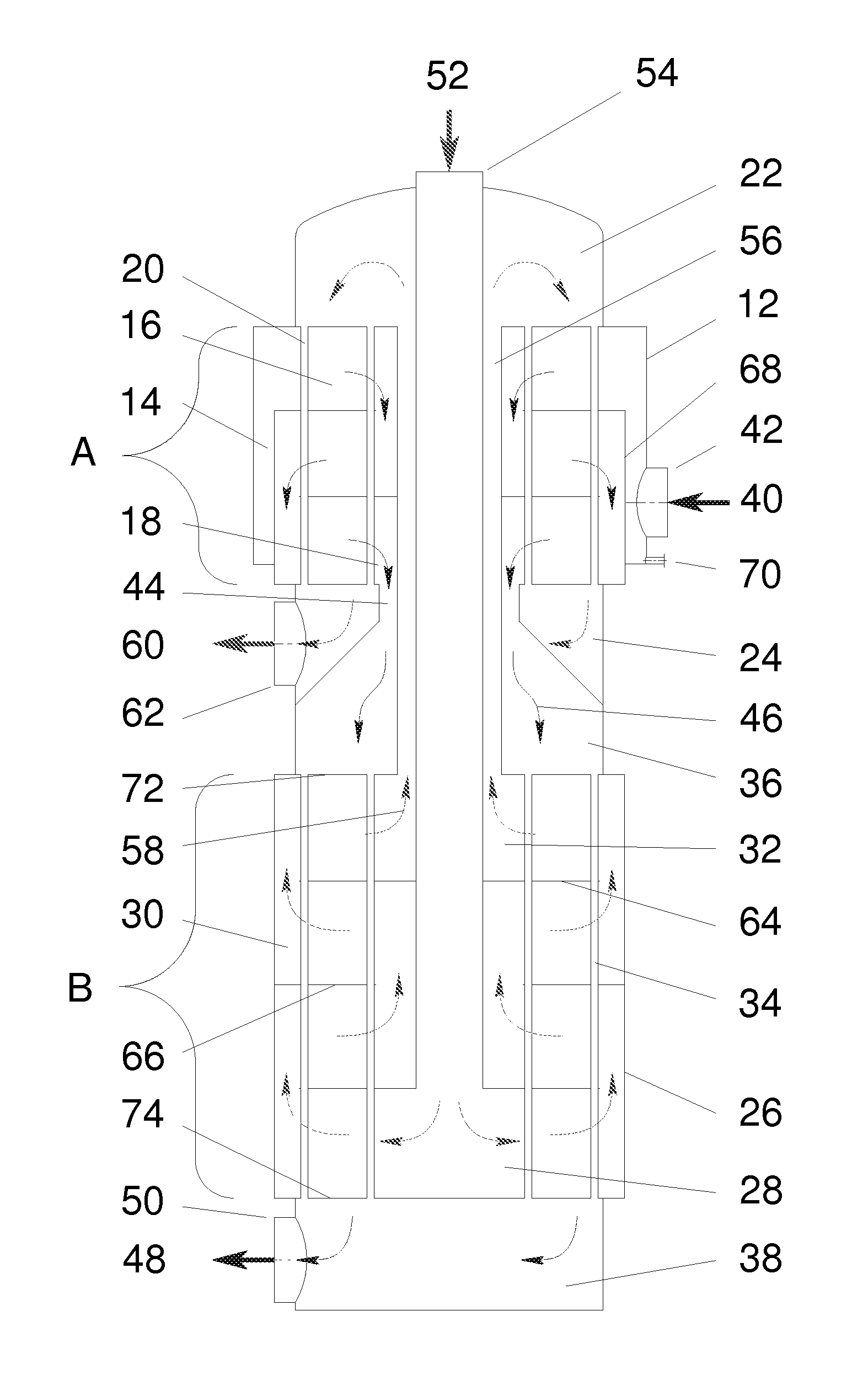
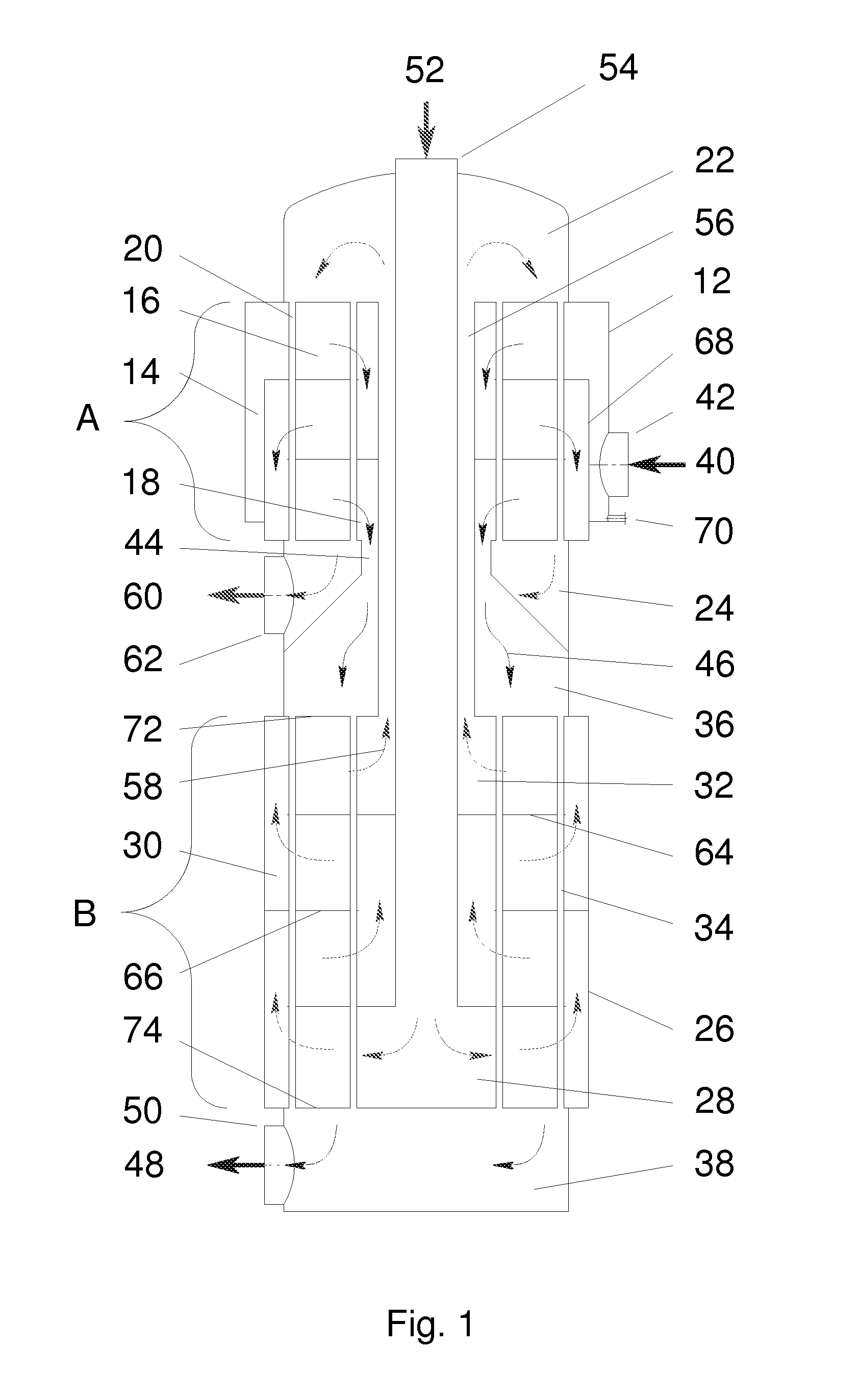
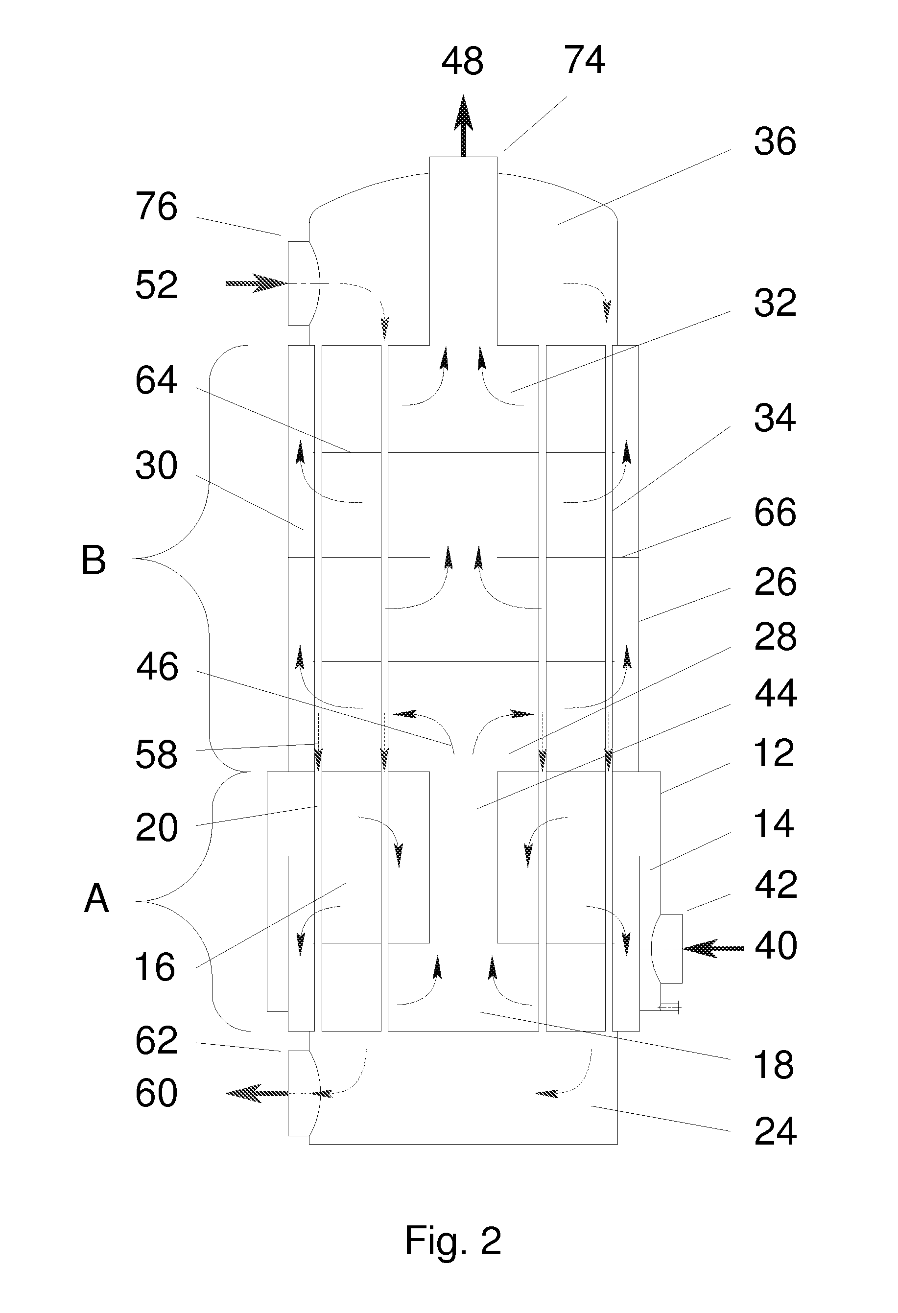
[0055]FIG. 1 shows a typical arrangement of a heat exchanger according to the invention comprised of two heat exchange sections, being parallel-flow section A and counter-flow section B.

[0056]Parallel flow section A is comprised of parallel flow shell 12, contained within which is parallel flow shell side inlet vestibule 14, parallel flow shell side 16, and parallel flow shell side outlet vestibule 18 where through said parallel flow shell side 16 there passes parallel flow section tubes 20 connecting parallel flow tube side inlet vestibule 22 and parallel flow tube side outlet vestibule 24.

[0057]Counter flow section B is comprised of counter flow shell 26, contained within which is counter flow shell side inlet vestibule 28, counter flow shell side 30, and counter flow shell side outlet vestibule 32 where through said counter flow shell side 30 there passes counter flow section tubes 34 connecting counter flow tube side inlet vestibule 36 and counter flow tube side outlet vestibule...


PUM


Abstract

A process for exchanging heat in a shell and tube gas-to-gas heat exchanger between a plurality of gases, said process comprising passing a cold first gas in parallel flow to a second hot gas to provide a warmer first gas; and passing said warmer first gas in counter-current flow to a hot third gas to provide a cooler said third gas. The invention provides increased minimum tube wall temperature within the exchanger for given process conditions while maintaining a high log mean temperature differential allowing for the prevention of corrosion from entrained corrosive vapours or entrained corrosive mist with a minimal increase in effective area.

Description

FIELD OF THE INVENTION[0001]This invention relates to shell and tube heat exchangers, more specifically to exchangers operating in service where a standard counter flow shell and tube heat exchanger would not be able to meet the required process conditions without experiencing dew point corrosion, more specifically to exchangers using a combination of counter flow and parallel flow throughout the exchanger to reduce the potential for dew point corrosion while being able to maintain a high thermal efficiency with only a minimal increase in effective area, and most specifically to gas to gas heat exchangers used to cool hot gases containing sulphur trioxide and / or acid vapour or heating cold gases containing sulphur dioxide and / or entrained acid mist.BACKGROUND OF THE INVENTION[0002]The invention relates to heat exchangers operating in potentially corrosive or high fouling conditions where said corrosion or fouling rates are highly dependent upon the tube wall temperature throughout t...

Claims


Application Information

Patent Timeline
IPC IPC(8): F28D7/00
CPCF28D7/1607F28F19/00F28F9/22
Inventor PEREZ, ORLANDO G.NORTON, DANIEL S.
Owner CHEMETICS
Why Eureka
Try Eureka