Split-flow, vertical ammonia converter

a vertical ammonia converter and ammonia flow technology, applied in the field of ammonia converters, can solve the problems of ammonia converters that are complicated, the impact of the cost, and achieve the effects of reducing the size of the reactor, reducing the catalyst fluidization potential, and eliminating the ineffective catalyst volum

Active Publication Date: 2006-07-25
KELLOGG BROWN & ROOT LLC
View PDF11 Cites 24 Cited by
  • Summary
  • Abstract
  • Description
  • Claims
  • Application Information

AI Technical Summary

Benefits of technology

[0005]The present invention is directed to a vertical, fixed-bed ammonia converter in which a fixed-bed catalyst zone is configured into two mechanically separated catalyst volumes and two gas streams that operate in parallel. The design maintains the ratio of gas flow to catalyst volume throughout the bed so that there is no catalyst effectiveness penalty compared to vertical radial-flow designs. The invention provides a reduction in reactor size s

Problems solved by technology

The size of the reactor, of course, has an impact on its cost.
Ammonia converters are complicated by the fact that ammonia synthesis from nitrogen and hydrogen gas is exothermic and the reactions take place at high temperatures and pressures.
These designs, however, generall

Method used


Image

  • Split-flow, vertical ammonia converter
  • Split-flow, vertical ammonia converter
  • Split-flow, vertical ammonia converter

Examples


Embodiment Construction

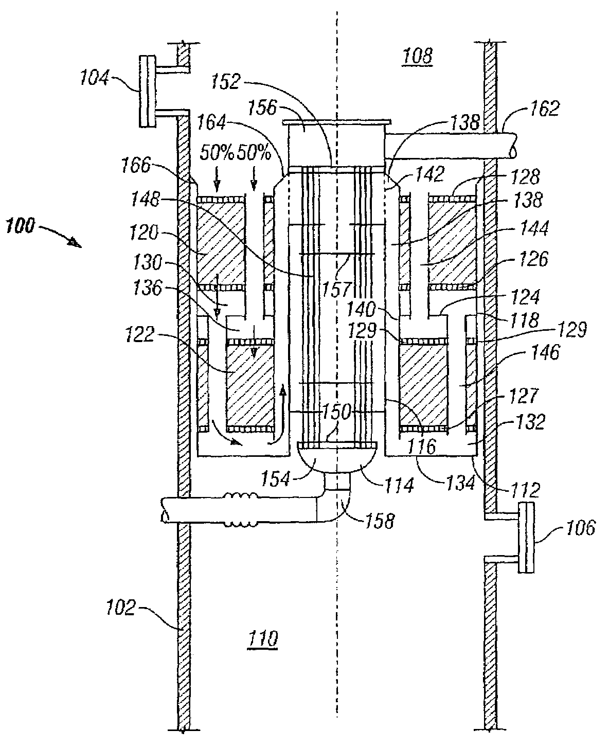
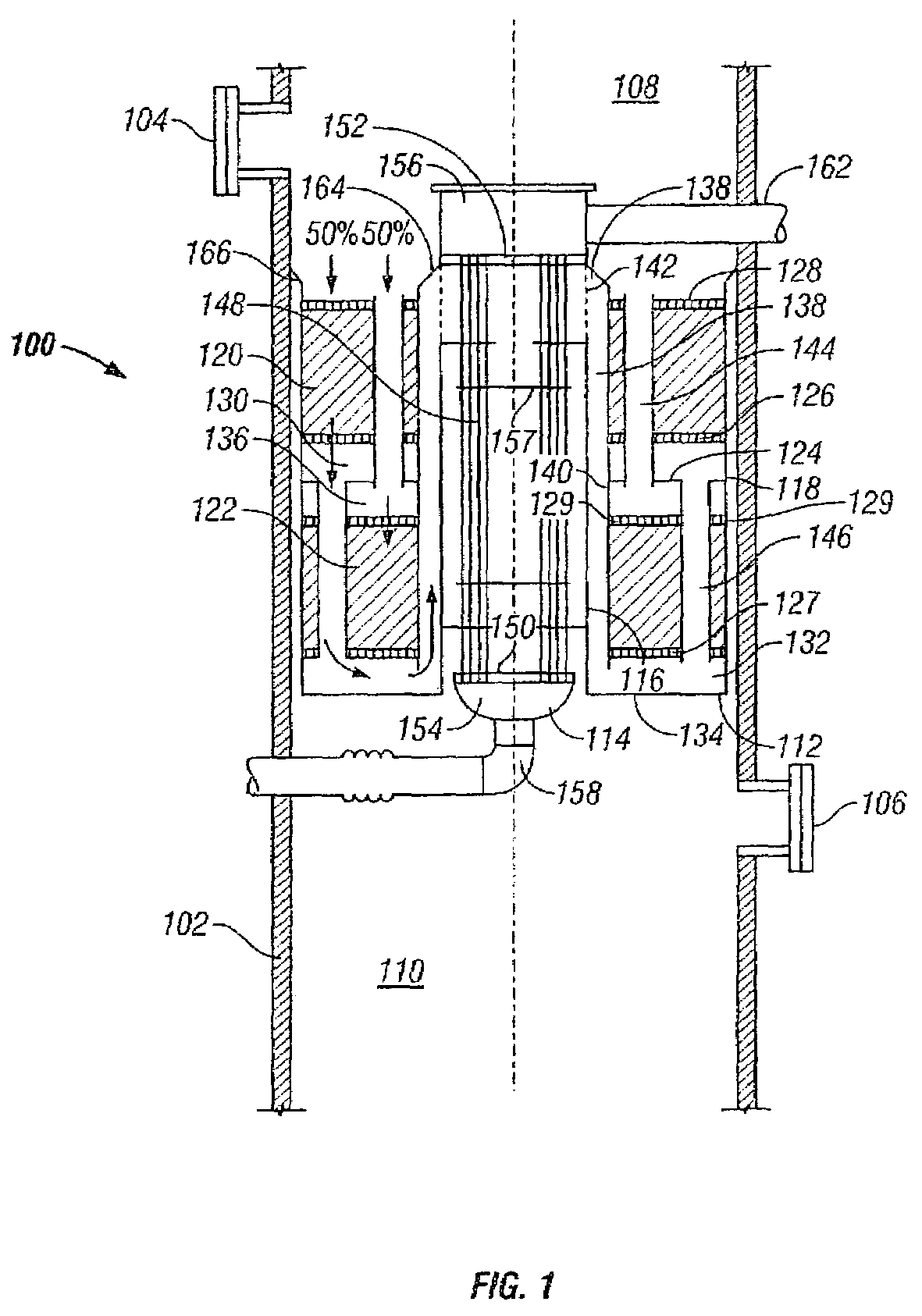
[0015]With reference to the drawings wherein the same reference numerals are used to refer to similar parts, FIG. 1 shows a catalyst zone 100 disposed within the vertical shell 102 of an ammonia converter according to one embodiment of the invention. Manways 104, 106 are provided for access at the respective gas inlet zone 108 and gas outlet zone 110.

[0016]A housing 112 is disposed concentrically about a shell-and-tube heat exchanger 114. The housing 112 has inner and outer concentric shrouds 116, 118. An intermediate shroud 140 is disposed outwardly of the inner shroud 116. The shrouds 118, 140 are disposed on either side of annular upper and lower catalyst volumes 120, 122. As used herein, the expression “catalyst volume” refers to the space intended to contain the ammonia conversion catalyst whether it actually contains the catalyst or has not yet been filled with catalyst. An annular partition plate 124 is disposed between the catalyst volumes 120, 122. Catalyst supports 126, 12...


PUM

PropertyMeasurementUnit
Lengthaaaaaaaaaa
Diameteraaaaaaaaaa
Volumeaaaaaaaaaa

Abstract

A vertical, fixed-bed ammonia converter wherein a fixed-bed catalyst zone is configured into two mechanically separated catalyst volumes and two gas streams that operate in parallel. The design maintains the ratio of gas flow to catalyst volume so that there is no catalyst effectiveness penalty. The catalyst beds and gas flow paths are configured so that gas flow is downward through each catalyst volume. Each fixed-bed catalyst zone in the present invention can hold the catalyst in an annular space formed between two concentric shrouds arranged around a shell and tube heat exchanger. The two catalyst beds associated with each zone are situated above one another along the length of an interstage heat exchanger. Pipes or conduits are disposed through the beds to effect the parallel gas flow configuration, or alternatively, annular flows are created via passages through the internal shrouds that contain the catalyst beds.

Description

BACKGROUND OF INVENTION[0001]This invention relates to ammonia converters for catalytically reacting a gaseous feed stream containing nitrogen and hydrogen to produce ammonia.[0002]Elaborate and sophisticated reactor designs have been developed for converting nitrogen and hydrogen in the gas phase in a fixed catalyst bed to form ammonia. The designs have attempted to optimize the ratio of gas flow to catalyst volume for maximum catalyst effectiveness. Even so, it is still desirable to reduce the reactor size relative to the ammonia production capacity. The size of the reactor, of course, has an impact on its cost.[0003]Ammonia converters are complicated by the fact that ammonia synthesis from nitrogen and hydrogen gas is exothermic and the reactions take place at high temperatures and pressures. Thus, interstage cooling is generally used between a series of catalyst zones to maintain kinetic and equilibrium conditions appropriate for optimum conversion efficiency. There must also be...

Claims


Application Information

Patent Timeline
IPC IPC(8): C01C1/00B01J8/04F28D1/00C01C1/02B01J23/745B01J35/00C01C1/04F28D7/16F28F9/26
CPCB01J8/0469B01J8/0496B01J23/745B01J35/0006C01C1/0423B01J8/0492F28F9/26B01J2208/00194B01J2208/00221B01J2208/0053B01J2208/00769B01J2208/00814B01J2208/00884B01J2208/025B01J2219/0002B01J2219/00038F28D7/16Y02P20/52
Inventor BLANCHARD, KENNETH LEWIS
Owner KELLOGG BROWN & ROOT LLC
Why Eureka
Try Eureka