Power supply device

a power supply device and power supply technology, applied in the direction of power conversion systems, dc-dc conversion, instruments, etc., can solve the problems of increasing the rate at an accelerated rate, the danger of excessive current occurring, damage to the power supply device, etc., and achieve the effect of reducing the size of the reactor

Inactive Publication Date: 2014-10-02
MITSUBISHI ELECTRIC CORP
View PDF0 Cites 4 Cited by
  • Summary
  • Abstract
  • Description
  • Claims
  • Application Information

AI Technical Summary

Benefits of technology

[0011]The present invention has been made aiming at reducing the size of a reactor in a

Problems solved by technology

However, when the load circuit is configured including a second DC power supply, if the on-time T1 and off-time T2 are deviated from the values originally required, due to external disturbances such as load fluctuation of the load circuit, there would be a danger of an excessive current occurring.
In general, a reactor inherently has drooping characteristics in which its inductance value de

Method used


Image

  • Power supply device
  • Power supply device
  • Power supply device

Examples


embodiment 1

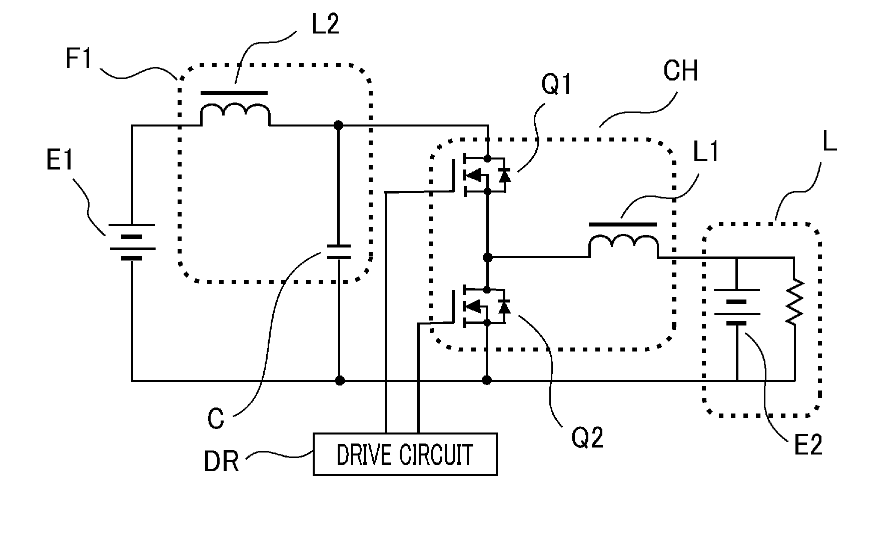
[0021]FIG. 1 shows the configuration of a power supply device according to Embodiment 1 of the present invention.

[0022]The power supply device according to this Embodiment 1 comprises: a first DC power supply E1; a load circuit L including a second DC power supply E2; a chopper circuit CH including a chopper switching element Q1, synchronous-rectification switching element Q2 and reactor L1 connected to the connection point between the switching elements Q1 and Q2; a filter circuit FI that includes a filter coil L2 and filter capacitor C and is interposed between the first DC power supply E1 and chopper circuit CH; and a drive circuit DR that controls turning on and off the chopper switching element Q1; wherein the drive circuit DR outputs a drive signal to turn on the switching element Q1 for a predetermined time T1 and turn off for a predetermined time T2 in an alternating manner, whereby input voltage from the first DC power supply E1 is descended to a predetermined voltage, so a...

embodiment 2

[0039]A power supply device according to Embodiment 2 is configured the same as that of Embodiment 1; however, the core of the filter coil L2 is made of a material that has large loss due to variation in magnetic flux but has high magnetic flux density compared to the core material of the reactor L1. An Fe-based material and ferrite-based material are selected for the cores of the filter coil L2 and reactor L1, respectively, in this Embodiment.

[0040]FIG. 3 shows waveforms of current flowing through the reactor L1 and filter coil L2 of the power supply device according to Embodiment 2. As shown in FIG. 3, each waveform demonstrates a DC current with an AC current superimposed thereon, and the amplitude of the ripple current through the reactor L1 is the larger of the two.

[0041]The amplitude of the ripple current causes variation in magnetic flux in the cores, which consequently causes loss (hysteresis loss and eddy current loss) in members constituting coils, particularly cores that ...

embodiment 3

[0044]The configuration of a power supply device according to Embodiment 3 is the same as that of Embodiment 1; however, closed-magnetic-circuit-type cores are used for both the reactor L1 and filter coil L2. Furthermore, the air gap of the core used for the reactor L1 is made wider than that of the core used for the filter coil L2.

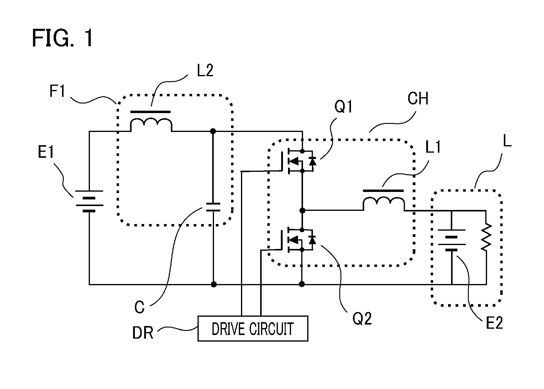
[0045]FIG. 5 shows the shapes of the cores and their DC-current-inductance characteristics in this Embodiment. E-shaped closed-magnetic-circuit-type cores are used for both the reactor L1 and filter coil L2; however, the air gap of the core used for the filter coil L2 is made wider to increase its magnetic resistance, whereby the filter coil is provided with characteristics in which its inductance value is secured even if high current flows therethrough, although the inductance value itself decreases.

[0046]In the configuration of Embodiment 3, by using the closed-magnetic-circuit-type cores, noise made by magnetic flux variation due to ripple components o...


PUM


Abstract

The size of a reactor is reduced in a power supply device whose load circuit includes a second DC power supply. A power supply device comprises: a chopper circuit CH connected between a first DC power supply E1 and load circuit L; and a filter circuit FI that includes a filter coil L2 and filter capacitor C and is interposed between the first DC power supply E1 and chopper circuit CH or between the second DC power supply E2 and chopper circuit CH; wherein the DC-current-inductance characteristic curve of the filter coil L2 and DC-current-inductance characteristic curve of the reactor L1 intersect each other, and the inductance value of the reactor L1 is made larger than that of the filter coil L2 in the region of current lower than a current value at the intersecting point.

Description

BACKGROUND OF THE INVENTION[0001]1. Field of the Invention[0002]The present invention relates to a power supply device connected to a load circuit including a DC power supply.[0003]2. Description of the Related Art[0004]This type of conventional power supply device as disclosed in, for example, Patent document 1 includes: a first DC power supply; a chopper circuit made up of a chopper switching element Q1, synchronous-rectification switching element Q2 and reactor L1 connected to the connection point between the switching elements Q1 and Q2; an output smoothing capacitor Cout; and a drive circuit that controls turning on and off the chopper switching element Q1. The drive circuit outputs a drive signal in such a way as to turn on the switching element Q1 for a predetermined time T1 and turn off for a predetermined time T2 in an alternating manner, whereby input voltage from the first DC power supply is descended to a predetermined output voltage, and current is supplied to a load ci...

Claims


Application Information

Patent Timeline
IPC IPC(8): H02M1/14H02M3/156
CPCH02M3/156H02M1/14H02M1/32H02M3/155
Inventor KIHARA, NOBUHIROYONEDA, ISAODAIGO, TORU
Owner MITSUBISHI ELECTRIC CORP
Why Eureka
Try Eureka