Distributed power harvesting systems using DC power sources

a technology of dc power source and distribution system, which is applied in the direction of dc source parallel operation, dc network circuit arrangement, semiconductor devices, etc., to achieve the effect of reducing energy losses and reducing current output from output terminals

Active Publication Date: 2011-11-10
SOLAREDGE TECH LTD
View PDF9 Cites 200 Cited by
  • Summary
  • Abstract
  • Description
  • Claims
  • Application Information

AI Technical Summary

Benefits of technology

[0010]According to further aspects, a method for power harvesting in a system including a photovoltaic panel with multiple sub-strings and a power converter. The sub-strings may be serially-connected photovoltaic cells. The power converter has input terminals and output terminals. The sub-strings may be connected in parallel to provide a parallel-connected DC power source. The input terminals of the converter may be attached to the parallel-connected DC power source. A singl

Problems solved by technology

Conversely, a serial connection may fail to provide the required current, so that several strings of serial connections may need to be connected in parallel to

Method used


Image

  • Distributed power harvesting systems using DC power sources
  • Distributed power harvesting systems using DC power sources
  • Distributed power harvesting systems using DC power sources

Examples


Embodiment Construction

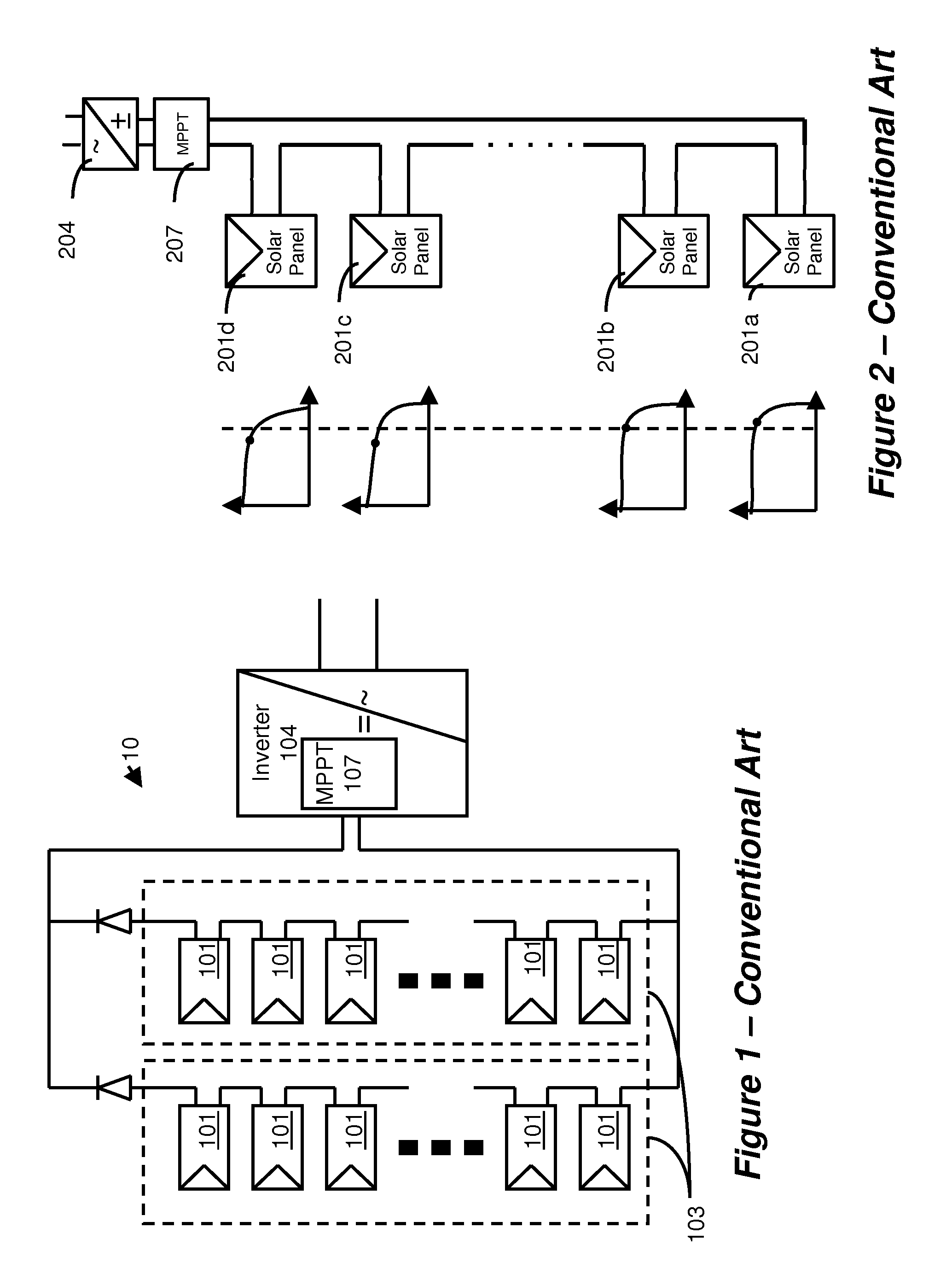
[0025]A conventional installation of solar power system 10 is illustrated in FIG. 1. Since the voltage provided by each individual solar panel 101 may be low, several panels may be connected in series to form a string of panels 103. For a large installation, when higher current may be required, several strings 103 may be connected in parallel to form the overall system 10. The solar panels may be mounted outdoors, and their leads may be connected to a maximum power point tracking (MPPT) module 107 and then to an inverter 104. The MPPT 107 may be typically implemented as part of the inverter 104. The harvested power from the DC sources may be delivered to the inverter 104, which converts the fluctuating direct-current (DC) into alternating-current (AC) having a desired voltage and frequency, which may be usually 110V or 220V at 60 Hz, or 220V at 50 Hz (It may be interesting to note the even in the US many inverters produce 220V, which may be then split into two 110V feeds in the elec...


PUM


Abstract

A photovoltaic panel with multiple photovoltaic sub-strings including serially-connected photovoltaic cells and having direct current (DC) outputs adapted for interconnection in parallel into a parallel-connected DC power source. A direct current (DC) power converter including input terminals and output terminals is adapted for coupling to the parallel-connected DC power source and for converting an input power received at the input terminals to an output power at the output terminals. The direct current (DC) power converter optionally has a control loop configured to set the input power received at the input terminals according to a previously determined criterion. The control loop may be adapted to receive a feedback signal from the input terminals for maximizing the input power. A bypass diode is typically connected in shunt across the input terminals of the converter. The bypass diode functions by passing current during a failure of any of the sub-strings and/or a partial shading of the sub-strings. The bypass diode may be a single bypass diode connected across the parallel-connected DC power source. The DC power converter may convert the input power at high current to the output power at a lower current. The output terminals may be connectible with wire cables to a load, and the DC power converter is configured to reduce energy loss through the wire cables to the load.

Description

CROSS REFERENCE TO RELATED APPLICATIONS[0001]The present application is a continuation-in-part application of U.S. patent application Ser. No. 11 / 950,271 filed Dec. 4, 2007 by the same inventors.BACKGROUND[0002]1. Field of the Invention[0003]The field of the invention relates generally to power production from distributed DC power sources, and particularly to a photovoltaic panel having series connected photovoltaic strings the outputs of which are connected in parallel.[0004]2. Related Arts[0005]The recent increased interest in renewable energy has led to increased research in systems for distributed generation of energy, such as photovoltaic cells (PV), fuel cells, batteries (e.g., for hybrid cars), etc. Various topologies have been proposed for connecting these power sources to the load, taking into consideration various parameters, such as voltage / current requirements, operating conditions, reliability, safety, costs, etc. For example, most of these sources provide low voltage o...

Claims


Application Information

Patent Timeline
IPC IPC(8): H02J1/10
CPCH01L31/02021H02J1/102Y02E10/566H02J7/35Y02E10/563H02J3/383H02J2300/24H02J3/381Y02E10/56H02J2300/26H02J3/46H02S40/34
Inventor ADEST, MEIRHANDELSMAN, LIORGALIN, YOAVFISHELOV, AMIRSELLA, GUYGAZIT, MEIR
Owner SOLAREDGE TECH LTD
Why Eureka
Try Eureka