Low cost blender control permitting low actuation force switches

Inactive Publication Date: 2011-11-10
ILLINOIS TOOL WORKS INC
View PDF2 Cites 0 Cited by
  • Summary
  • Abstract
  • Description
  • Claims
  • Application Information

AI Technical Summary

Benefits of technology

[0007]The present invention provides circuitry implementing electronic logic that is suitable for use with low-cost blenders having low-voltage membrane switches and the like. Low-cost power conversion necessary for such electronic logic is obtained by using two different regulation circuits. One circuit provides low power dissipation and low power suitable for standby use and for initial switching of power to the motor. The second circuit provides much higher power dissipation but also higher power suitable to maintain switching of power to the motor. The second circuit is connected to receive power only when the motor is connected. In this way, average power dissipation of power conversion is kept low by the intermittent motor cycling typical of a blender.
[0009]It is thus a feature of at least one embodiment of the invention to provide low-cost power conditioning with low standby power dissipation.
[0013]It is thus a feature of at least one embodiment of the invention to convert line voltage to low-voltage through simple resistive voltage reduction without excess power dissipation. Because the second powered conditioning circuit is only active when the motor is active, higher power dissipation and thus higher power production is possible in the second power conditioning circuit while maintaining a low average power dissipation.

Problems solved by technology

In contrast, electromechanical logic can result in buttons that are relatively hard to push, require substantial actuation distance, and are hard to seal against environmental contamination.
Low-cost blenders often cannot support electronic logic, principally because of the cost of circuitry necessary to convert 120 VAC power used for the blender motor to regulated, low-voltages required for typical logic circuits, and because of the cost of integrated circuits to implement the logic.

Method used


Image

  • Low cost blender control permitting low actuation force switches
  • Low cost blender control permitting low actuation force switches
  • Low cost blender control permitting low actuation force switches

Examples


Embodiment Construction

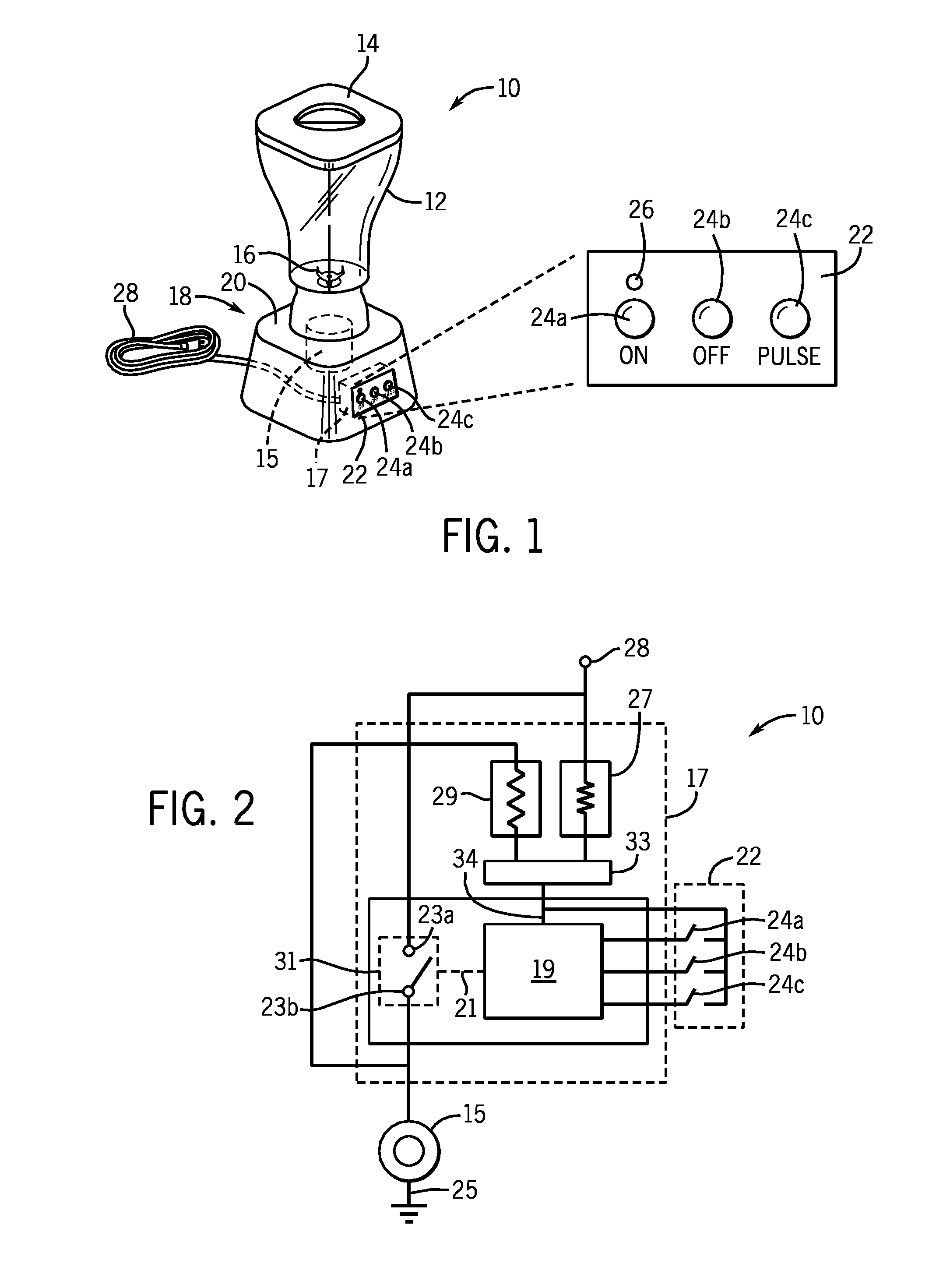
[0024]Referring now to FIG. 1, a blender 10 may include a glass, plastic or metal blender container 12 typically having a removable lid 14 permitting foods (not shown) to be inserted in the container 12 and blended by an internally contained blender knife 16.

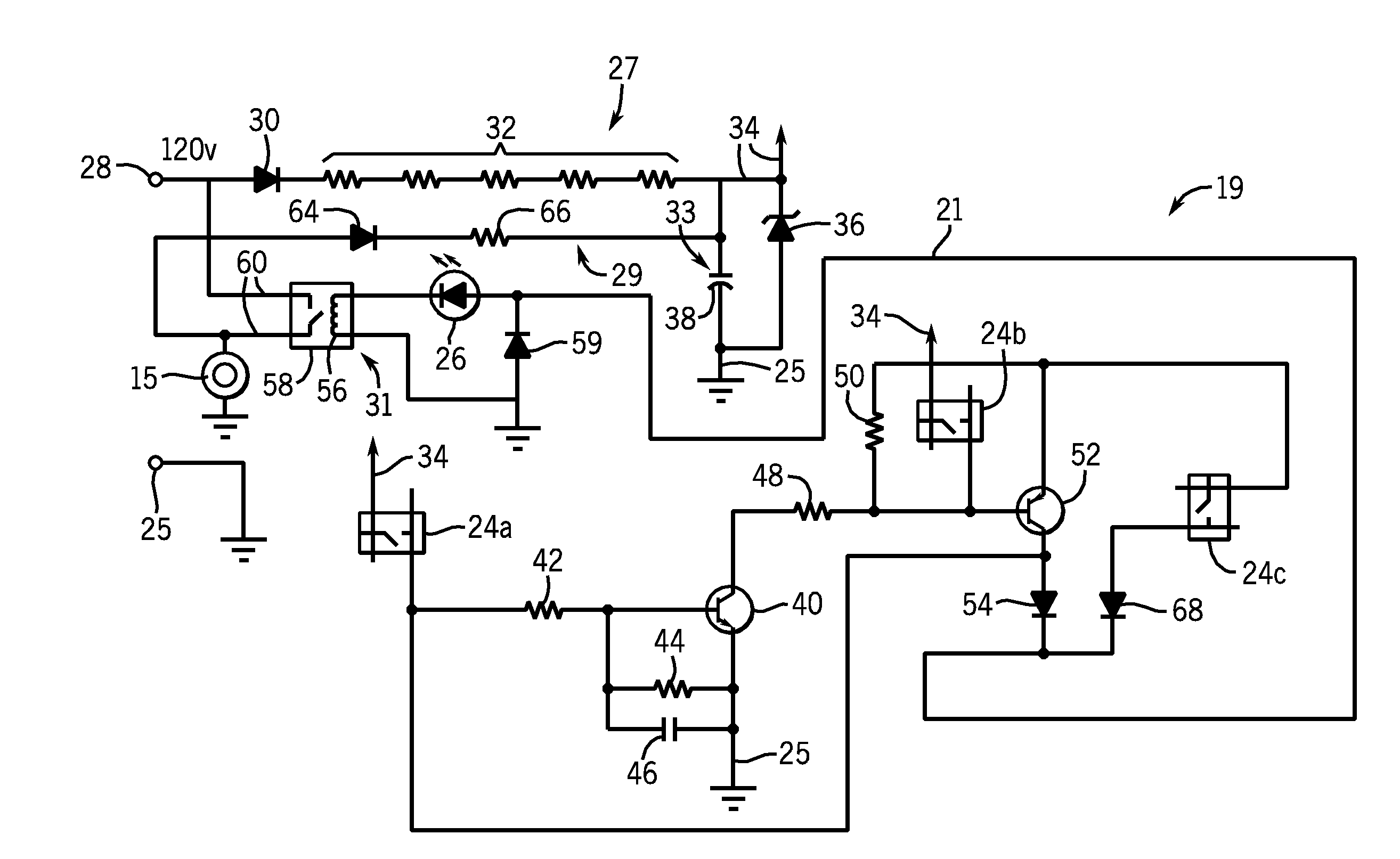
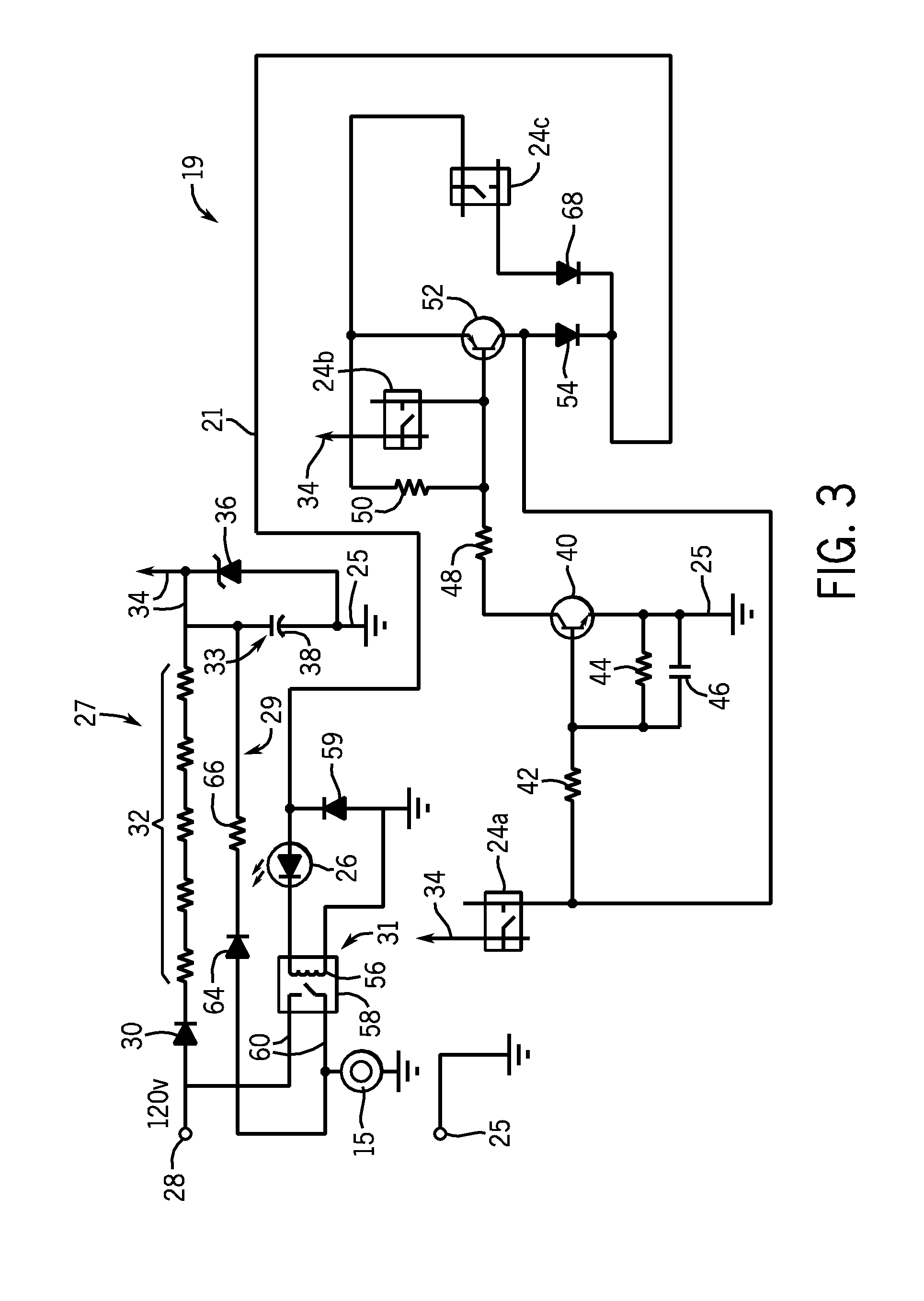
[0025]The blender container 12 may sit on top of a blender power unit 18 having a housing 20 containing a motor 15 and control electronics 17 to be described in more detail below. The front of the housing 20 may present a control panel 22 having a set of switches 24, preferably “tactile” type membrane switches, each providing momentary contact, single pole single throw operation and suitable for low-voltage control. As is understood in the art, such membrane type switches may include an outer membrane providing a hermetic seal against environmental contamination and may use contacts formed from printed circuit traces typically on at least one flexible membrane. Such membrane switches are low-voltage devices operating, for exampl...


PUM


Abstract

A control circuit for a blender provides low-cost power conditioning through the use of a high resistance which provides temporary power for operation of low-voltage logic circuitry and low-voltage switches for a time sufficient to switch the motor on, and a lower resistance which provides sufficient power for maintaining the motor on state indefinitely as instructed by the low-voltage logic circuitry. Low average power dissipation is provided by powering the low-voltage logic circuitry and low-voltage switches using the high resistance in a standby mode and switching in the lower resistance only when the motor is activated.

Description

CROSS-REFERENCE TO RELATED APPLICATIONS[0001]This application claims the benefit of U.S. provisional application 61 / 142,815, filed Jan. 6, 2009, the disclosure of which is incorporated herein by reference.BACKGROUND OF THE INVENTION[0002]The present invention relates generally to household appliances and, in particular, to control circuitry for small appliances such as blenders and the like.[0003]Electrical controls for food blenders of the type used for preparation of meals in a kitchen typically include a set of electrical switches or buttons on a front panel that may be used to control the blender motor. Such switches normally provide at least three operating modes: a “pulse” mode in which the blender operates only while a “pulse” button is pressed, an “on” mode in which the blender operates continuously after the “on” button is pressed and until released by pressing of an “off” button, and an “off” mode which cancels the “on” mode when the “off” button is pressed.[0004]These ele...

Claims


Application Information

Patent Timeline
IPC IPC(8): H02P6/00
CPCA47J43/085A47J43/0716
Inventor LARSON, ERIC K.TUCKER, ANDY W.
Owner ILLINOIS TOOL WORKS INC
Why Eureka
Try Eureka