Visual prosthesis implant

Inactive Publication Date: 2011-08-18
NXP BV
View PDF14 Cites 0 Cited by
  • Summary
  • Abstract
  • Description
  • Claims
  • Application Information

AI Technical Summary

Benefits of technology

[0006]It is an object of the present invention to provide a visual prosthesis implant which provides the required low power dissipation, a small size, real-time image processing, and (re-)programming flexibility. Further, the visual prosthesis implant shall allow full integration for e.g. intraocular implantation.
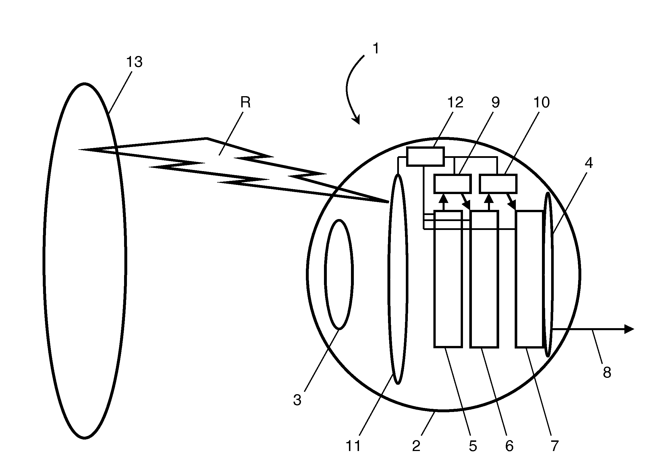
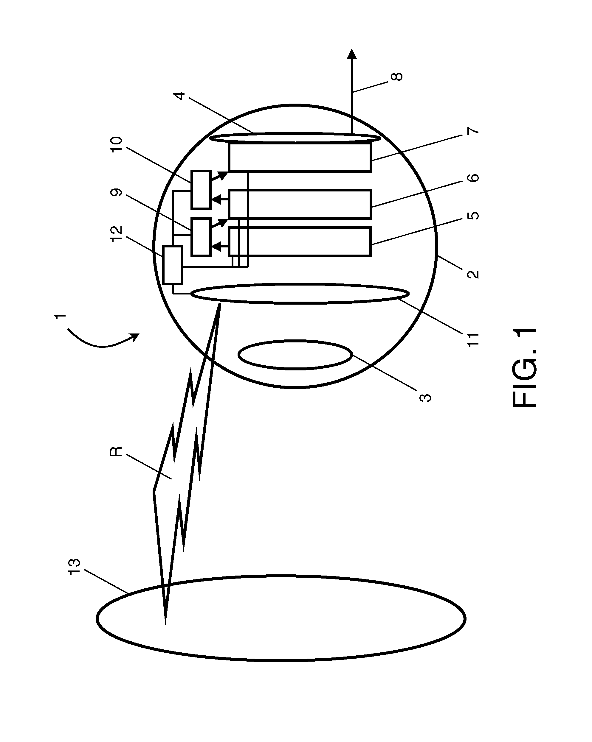
[0007]This object is solved by a visual prosthesis implant according to claim 1. The visual prosthesis implant comprises: an SIMD-based processor array adapted for receiving image signals from an image sensor and outputting processed signals, and a bio-compatible electrode implant receiving the processed signals and adapted for coupling to neurons. Thus, the visual prosthesis implant comprises an SIMD-based (single-instruction multiple data) processor array. Processor arrays based on the SIMD processing paradigm provide very high computational efficiency in embedded image processing applications. Thus, low power dissipation, small size, real-time image processing, and programming flexibility can all be simultaneously achieved by making use of on-chip SIMD processing. The high degree of parallelism of n processing cores (with n being an integer) in SIMD processing (a core being typically called a processing element (PE) in SIMD designs) allows for a lower supply voltage for the same performance because only a clock frequency f which is 1 / n times the clock frequency of a single core realization is needed, and operation at such a lower clock frequency can be achieved at a lower supply voltage. Although the lower clock frequency f for charging and discharging a chip interconnect to some extent cancels out against the factor n increase in chip area A required for provision of n cores, the power dissipation of a multi-core realization can, for the same performance, still be significantly lower as compared to a single-core system (or a system comprising a few cores). This is due to the fact that the supply voltage contributes quadratically to the power dissipation. As a consequence, the required low power dissipation can be achieved using SIMD-based processor arrays. The parallelism of SIMD processing is also a perfect match to typical low level image processing algorithms in which typically all pixels are subjected to the same set of transformations while any remaining differences in pixel processing can be accounted for through transformation parameters and masking bit vectors. Further, the SIMD architecture offers a large degree of programming flexibility for adapting the performance of the visual prosthesis implant as compared to e.g. an ASIC design. A combination of an image sensor, the SIMD-based processor array, and a bio-compatible electrode array for coupling to neurons offers great advantages over the existing art. In particular, fully integrated intraocular implants can be realized with this combination of features. However, in principle the image sensor can be either provided separate from the visual prosthesis implant or may be integrated in the visual prosthesis implant.
[0008]Preferably, the SIMD-based processor array is adapted to output signals conditioned to match bio-compatible electrode characteristics. In this case, only a basic digital-analog converter (DAC) needs to be applied to convert digital signal levels and codes to appropriate voltage, current, and charge injection rates which further helps in reduction of the overall device area and power consumption.
[0013]Preferably, the visual prosthesis implant is structured such that the SIMD-based processor array receives digital image signals directly from an image sensor having a digital output or from an analog image sensor via an analog-digital converter. Such an arrangement allows achieving a particularly small overall volume which is advantageous for e.g. intraocular implants.
[0014]Preferably, the visual prosthesis implant is adapted to be wirelessly provided with electrical power. In this case, the visual prosthesis implant does not even require wiring to the exterior for power supply, thus reducing risks coming along with external wiring such as possible infections, wiring wear, etc.
[0015]According to an aspect, the visual prosthesis implant comprises a low-bandwidth wireless communication unit. A low-bandwidth wireless communication unit also comprises low power dissipation and can e.g. be realized through the zigbee protocol. Such a wireless communication unit may be adapted to allow changing of operation settings of the visual prosthesis implant, uploading new firmware and programs, imposing test images on the electrode array, and reporting device and electrode status or debugging information such that all these features can be realized without requiring wiring to the external.

Problems solved by technology

However, with respect to the specific envisaged applications, these applied techniques are highly inefficient in terms of power consumption, performance, and chip area.
In particular, this inefficiency has frustrated system size reduction and system integration.
However, such a design has several drawbacks such as the limited flexibility to program individualized processing as required to account for individual differences between different patients.
Further, electrode coupling to neurons may degrade over time and may vary with respect to individual electrodes from patient to patient.
Furthermore, signal processing for electrode stimulation in particular requires high programming flexibility.

Method used


Image

  • Visual prosthesis implant
  • Visual prosthesis implant

Examples


Embodiment Construction

[0019]FIG. 1 schematically shows a visual prosthesis implant according to an embodiment which is an intraocular implant. As can be seen in FIG. 1, all components of the visuals prosthesis implant 1 according to the embodiment are provided in the interior of a human eye 2. In the embodiment, all components are situated between the retina 4 and the lens 3. In other embodiments, the electrode array may be positioned behind the retina, as with subretinal implants, and various other components could also be positioned behind the retina. In FIG. 1, a situation is shown in which the lens 3 is the natural lens of the eye 2 and an image sensor 5 is provided in the focal plane of the natural lens 3 near the retina 4. However, instead of using the natural lens 3, image acquisition can also be realized by the image sensor 5 in combination with an artificial lens system. Further, an SIMD-based processor array 6 is provided which is operatively connected to the image sensor 5. The SIMD-based proc...


PUM


Abstract

A visual prosthesis implant (1) is provided which comprises an SIMD-based processor array (6) adapted for receiving image signals from an image sensor (5) and outputting processed signals, and a bio-compatible electrode implant (7) receiving the processed signals and adapted for coupling to neurons. Using the SIMD-based processor array (6) provides high performance at small power dissipation and small chip area such that a fully implantable is visual prosthesis is achieved.

Description

FIELD OF THE INVENTION[0001]The invention relates to a visual prosthesis implant. More particular, the invention relates to a visual prosthesis implant comprising a bio-compatible electrode implant for coupling to neurons.BACKGROUND OF THE INVENTION[0002]In recent years, many researchers around the world have been working on retinal implants and cortical implants to restore vision in human patients. In particular, electronic retinal prostheses are being developed for patients affected by common causes of blindness that only damage the light receptors in the retina, such as RP (Retinitis Pigmentosa) and AMD (age-related macular degeneration). Further, cortical implants and deep brain implants for restoring sight to blind people are being developed.[0003]WO 03 / 090166 A2 discloses a permanent retinal implant device using a NGC array hybridized to a silicon chip, the image being simultaneously generated within each cell through a photon-to-electron conversion using a silicon photodiode....

Claims


Application Information

Patent Timeline
IPC IPC(8): A61F2/16A61F2/14
CPCA61N1/36046A61N1/0543
Inventor MEIJER, PETER BARTUS LEONARD
Owner NXP BV
Why Eureka
Try Eureka