Synchronous oscillator, clock recovery apparatus, clock distribution circuit, and multi-mode injection circuit

a clock recovery and injection circuit technology, applied in the direction of generating/distributing signals, pulse manipulation, pulse techniques, etc., can solve problems such as error detection of reception data, achieve low power dissipation, increase transfer rate and low power dissipation, and reduce the power dissipation of clock recovery circuits.

Inactive Publication Date: 2011-03-17
SONY CORP
View PDF1 Cites 6 Cited by
  • Summary
  • Abstract
  • Description
  • Claims
  • Application Information

AI Technical Summary

Benefits of technology

[0031]For lowering the power dissipation of the clock distribution circuit, a method of distributing a clock signal by narrowing the amplitude of the clock signal is sometimes used. However, this approach presents a problem of the increased jitter, thereby preventing digital circuits from being operated at high speeds.
[0032]Therefore, the embodiments of the present invention address the above-identified and other problems associated with related-art methods and apparatuses and solve the addressed problems by providing a synchronous oscillator, clock recovery apparatus, a clock distribution circuit, and a multi-mode injection circuit that are configured to be able to correctly execution edge detection even if the edge positions are fluctuated in clock signals and reception data signals, thereby realizing increased transfer rates and low power dissipations.

Problems solved by technology

While this fluctuation is effective in recovering reception data because this fluctuation corresponds to the fluctuation of a reception data signal, an abrupt recovery clock phase fluctuation may cause an erroneous detection of reception data.

Method used


Image

  • Synchronous oscillator, clock recovery apparatus, clock distribution circuit, and multi-mode injection circuit
  • Synchronous oscillator, clock recovery apparatus, clock distribution circuit, and multi-mode injection circuit
  • Synchronous oscillator, clock recovery apparatus, clock distribution circuit, and multi-mode injection circuit

Examples


first embodiment

(1) The First Embodiment

[0090]Configuration of the Synchronous Oscillator:

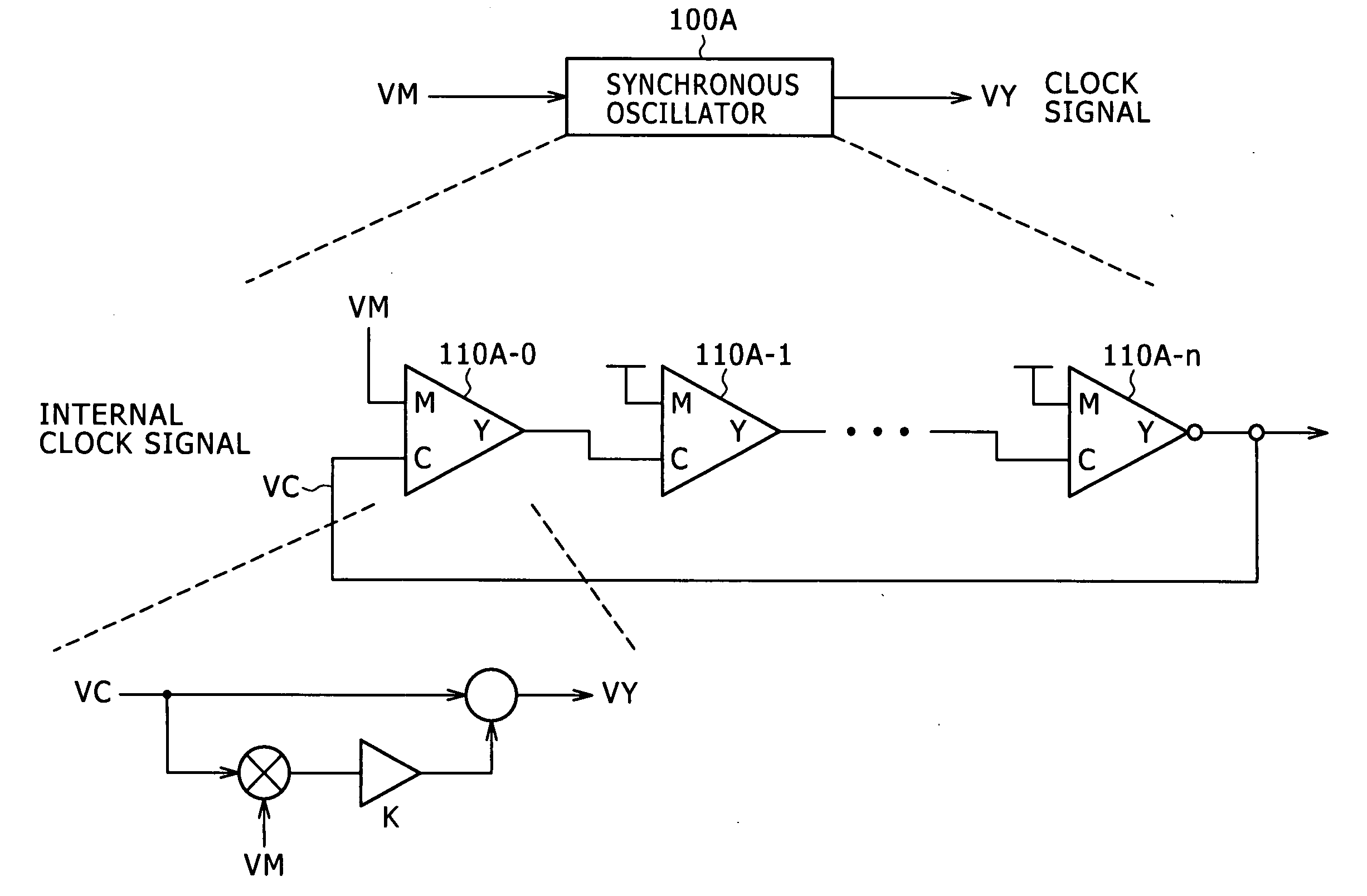
[0091]Now, referring to FIG. 4, there is shown a block diagram illustrating an exemplary configuration of a synchronous oscillator practiced as the first embodiment of the invention.

[0092]A synchronous oscillator 100 is configured by a ring oscillator 120 that includes at least one injection circuit 110 as shown in FIG. 4.

[0093]The synchronous oscillator 100 functions as a voltage-controlled oscillator (VCO) with the oscillation frequency thereof controlled by a oscillation frequency control signal FCV.

[0094]The ring oscillator 120 shown in FIG. 4 has the 2-input injection circuit 110 at the first stage, followed by cascade-connected delay circuits 121-1 through 121-n connected to the output of the injection circuit 110, the output of the delay circuit 121-n at the last stage being connected to one of the input of the injection circuit 110 at the first stage.

[0095]The ring oscillator 120 is basically formed su...

second embodiment

(2) The Second Embodiment

[0205]The First Exemplary Configuration of the Clock Recovery Apparatus

[0206]Referring to FIG. 14, there is shown a block diagram illustrating an exemplary configuration of the clock recovery apparatus practiced as the second embodiment of the invention.

[0207]A clock recovery apparatus 200 practiced as the second embodiment of the invention has an edge detector 210 and a synchronous oscillator 220.

[0208]For the synchronous oscillator 220, the synchronous oscillator 100 associated with the first embodiment described above is applied.

[0209]Therefore, the description of the detail configuration and function of the synchronous oscillator 220 is skipped here.

[0210]The edge detector 210 detects the edge of reception data signal RDT and outputs resultant edge detection signal SED to the synchronous oscillator 220 as an injection signal (VM).

[0211]Referring to FIG. 15, there is shown a circuit diagram illustrating an exemplary configuration of the edge detector asso...

third embodiment

(3) The Third Embodiment

[0231]The Second Exemplary Configuration of the Clock Recovery Apparatus

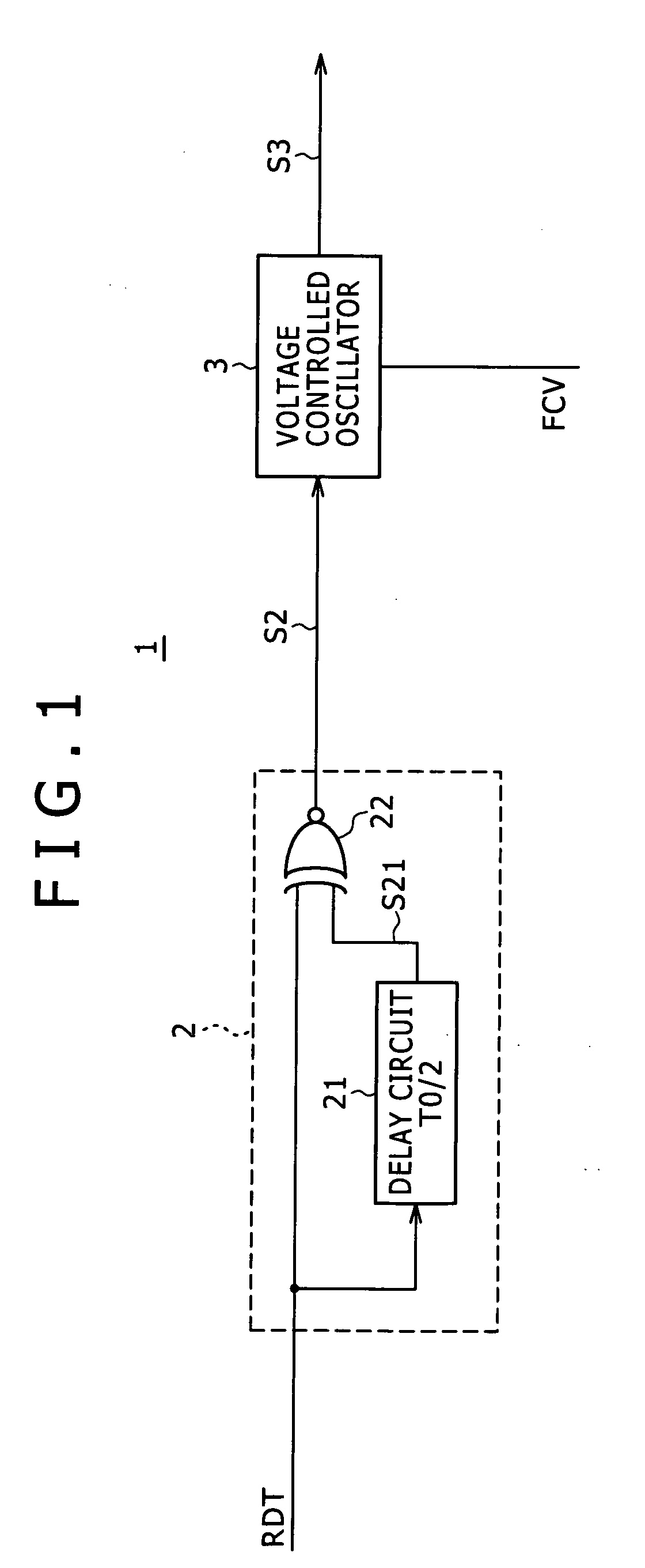
[0232]Referring to FIG. 18, there is shown a block diagram illustrating an exemplary configuration of a clock recovery apparatus practiced as the third embodiment of the invention.

[0233]A clock recovery apparatus 200A associated with the third embodiment has an edge detector 210A and a synchronous oscillator 220A as shown in FIG. 18.

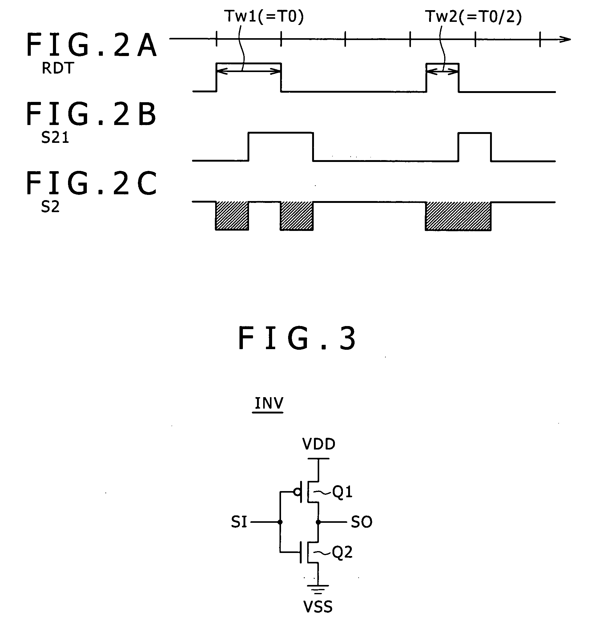
[0234]The edge detector 210A detects the rising edge of reception data signal RDT to generate rising-edge detection signal SEDR indicative of the presence or absence of rising edge and falling-edge detection signal SEDF indicative of the presence and absence of falling edge.

[0235]The edge detector 210A outputs generated rising-edge detection signal SEDR and falling-edge detection signal SEDF to the synchronous oscillator 220A.

[0236]Exemplary Configuration of the Edge Detector

[0237]FIGS. 19A through 19D show circuit diagrams indicative of exemplary configuratio...


PUM


Abstract

Disclosed herein is a synchronous oscillator including at least one injection circuit having an injection signal input terminal, an internal clock signal input terminal, and a clock output terminal, and at least one delay circuit cascaded to the injection circuit.

Description

BACKGROUND OF THE INVENTION[0001]1. Field of the Invention[0002]The present invention relates to a synchronous oscillator for outputting clock signals, a clock recovery apparatus, a clock distribution circuit, and a multi-mode injection circuit.[0003]2. Description of the Related Art[0004]Recently, in the field of digital transmission, demands for transferring massive data at high speeds and with low power dissipation have been increasing. For the interface for this data transfer, clock recovery apparatuses are in wide use.[0005]At the same time, the resistance against jitters is desired of high-speed interfaces due to the increased jitter components contained in signals caused by increased transfer rates.[0006]The clock recovering includes those based on PLL application and the selection or generation of the clock of a phase locked with a reception data signal from a multi-phase clock signal.[0007]However, these clock recovery schemes involve a problem that a high-speed operation r...

Claims


Application Information

Patent Timeline
Patent Type & Authority Applications(United States)
IPC IPC(8): H03L7/02H03K3/03H03K3/356H03K5/13H03K19/20H03L7/00H03L7/08H04L7/02
CPCG06F1/12H03K3/0315H03L7/0995H03L7/0807H03L7/0805H03K5/13H03L7/00H03L7/02H04L7/033
Inventor MARUKO, KENICHI
Owner SONY CORP
Why Eureka
Try Eureka