
Method for image restoration in a computer vision system

Inactive Publication Date: 2011-11-10
HONDA MOTOR CO LTD
View PDF9 Cites 50 Cited by
  • Summary
  • Abstract
  • Description
  • Claims
  • Application Information

AI Technical Summary

Benefits of technology

[0009]In view of such problems of the prior art, a primary object of the present invention is to provide a method for improving robustness of image processing.
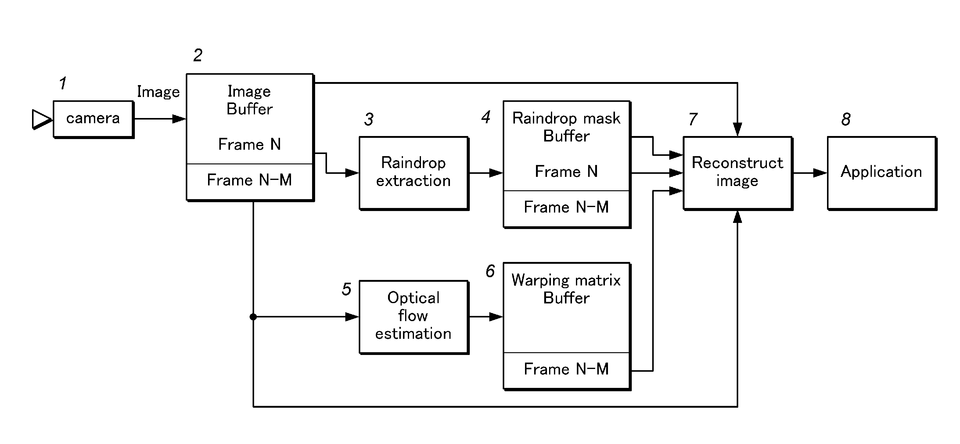
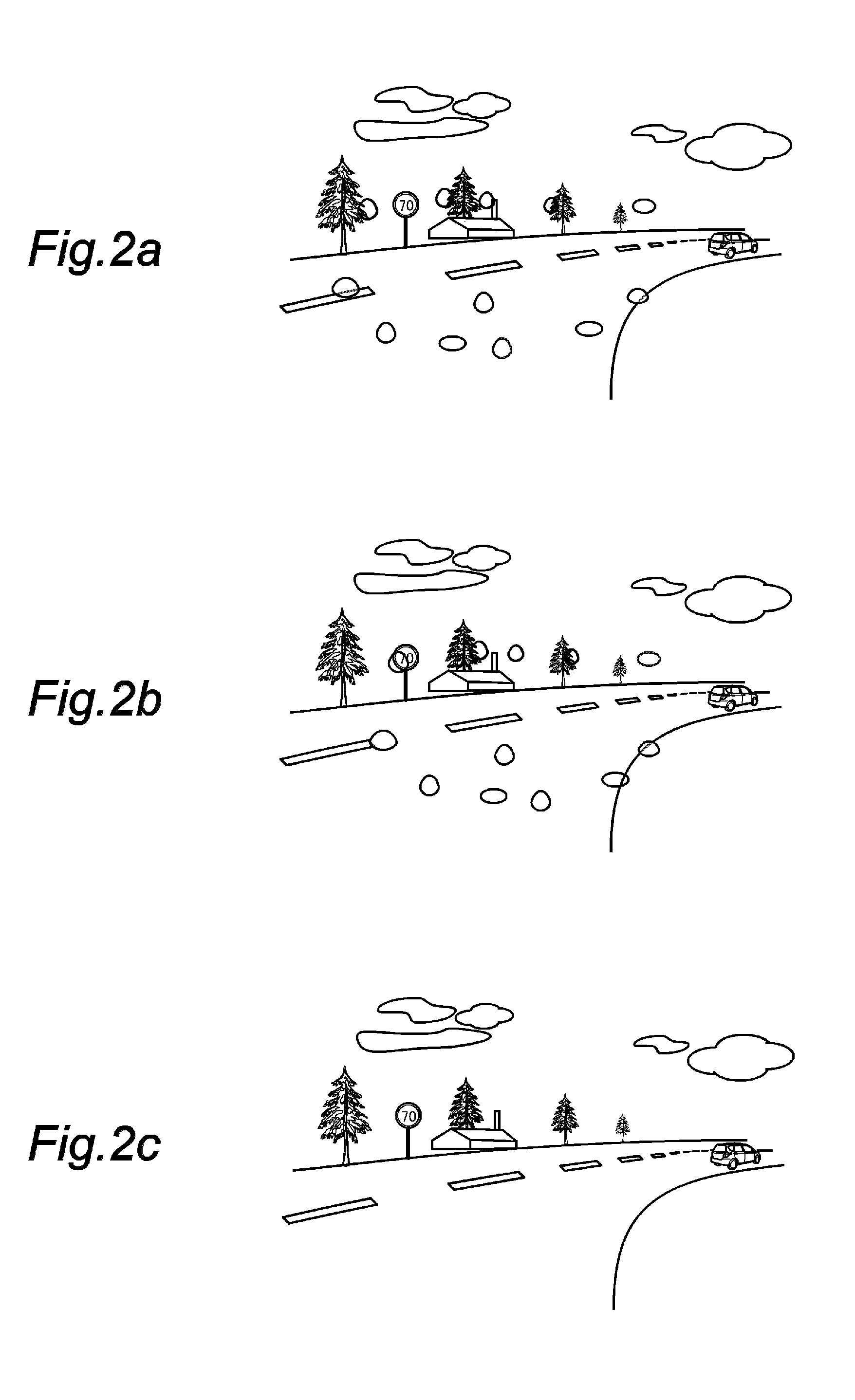
[0012]Thereby, the occluded part of the image can be reconstructed by making use of redundant optical information. More specifically, this is achieved by use of temporal and spatial mapping techniques to reconstruct locally distorted image areas or to exclude affected areas from further image processing. These mapping techniques overcome problems of prior art like increased latency times. Thus, a full image can be made available to the computer vision system with a minimum latency time by using minimum hardware resources. Typically, the first and second image are captured through a substantially transparent sheet that could be optically occluded by contamination, and the contamination may include a member selected from a group consisting of a raindrop, a stone-chipping and a smear deposit on the transparent sheet.
[0014]This is based on stereo disparity estimation which normally provides depth information of the captured image, but additionally provides certain spatial redundancy enabling the reconstruction of optical occlusion.
[0016]This is based on optical flow estimation. When the object is stationary, and the images thereof are captured by a camera or cameras carried by a moving platform such as a vehicle, the object appears to move in the view of the camera due to the relative motion between the object and moving platform whereas the optical occlusion remains stationary in the view of the camera. Therefore, a part of the object which is optically occluded at one time point may not be so in a subsequent or preceding time point. This temporal redundancy enables the reconstruction of the optically occluded image.

Problems solved by technology

In case of local image distortions this requirement may not be fulfilled and hence, these algorithms may “lose” the object of interest.
Local image distortions can be caused by raindrops on the windshield, contamination of windshield, stone-chippings, and other disturbed areas on the windshield.
Effects of bad weather (e.g. raindrops on the windshield), contaminated areas as well as small damages (stone-chippings) lead to several types of image disturbances like (partial) occlusion of image regions, blur, and local distortions.
As a consequence feature extraction performance will deteriorate as well as the detection performance of following modules.
However, this method can hardly be applied to image restoration in rainy weather because there will be raindrops on almost every image and as a result the latency time for image processing will increase due to the need to wait for the next image frame or an image frame without noise.

Method used


Image

  • Method for image restoration in a computer vision system
  • Method for image restoration in a computer vision system
  • Method for image restoration in a computer vision system

Examples


Embodiment Construction

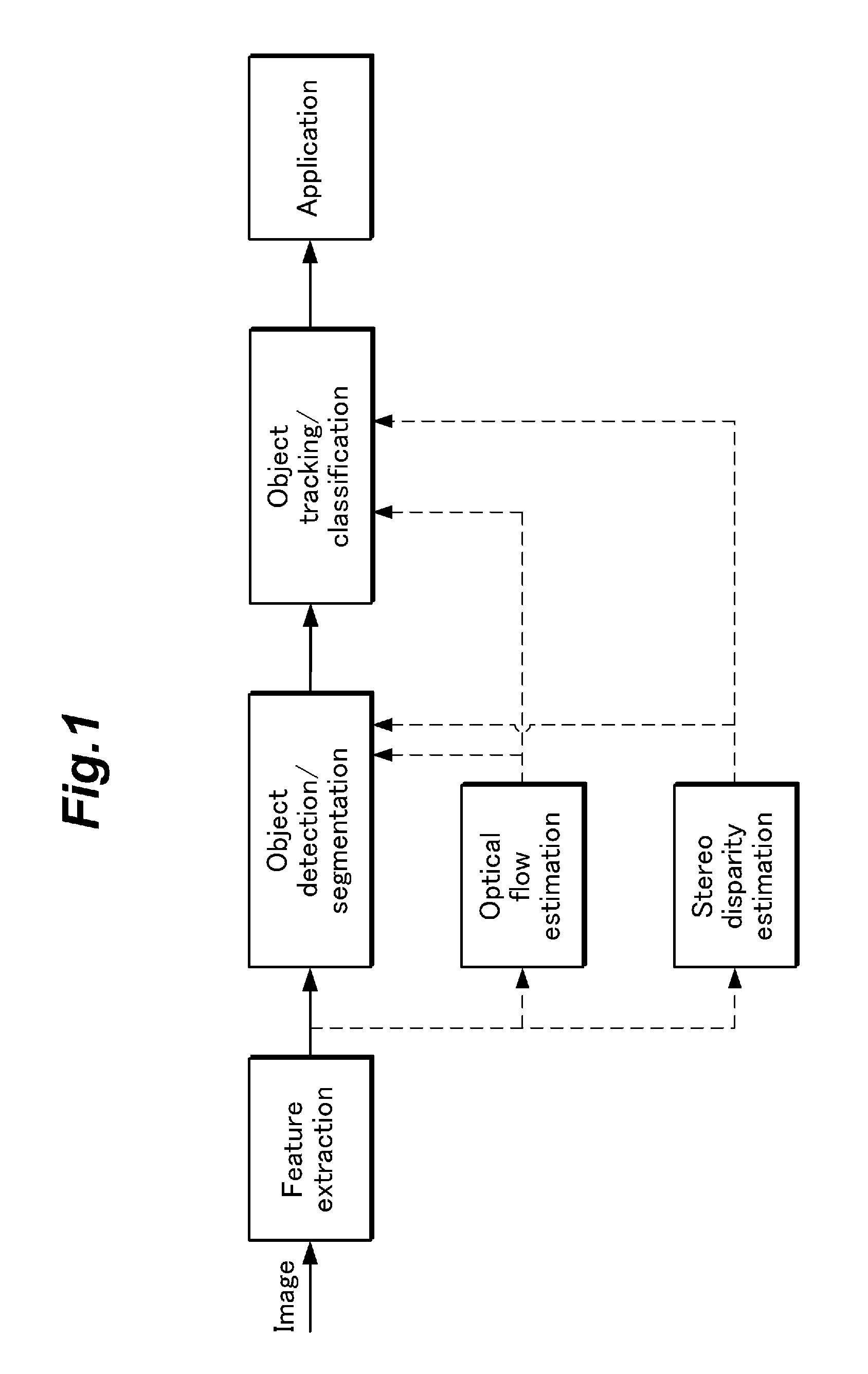
[0037]FIG. 1 illustrates the basic concept of the present invention. The present invention is typically employed on a vehicle to capture the image of an external view for the purposes of lane tracking, detection of obstacles, detection of traffic signs or tracking a leading vehicle for maintaining a suitable distance to it, among other possibilities.

[0038]The vehicle is equipped with a camera (which may be a stereoscopic camera) and a computer for processing the image data acquired by the camera. The image acquired by the camera is processed by a computer, and features are extracted therefrom. The features are further processed by various techniques such as object detection / segmentation and object tracking / classification. The required image handling processes are executed by suitable computer programs running on the computer. The acquired images are sometimes contaminated by optical occlusions such as raindrops, stone-chippings and dirt on the windshield. In such a case, the occlude...


PUM


Abstract

A vehicle is equipped with a camera (which may be a stereoscopic camera) and a computer for processing the image data acquired by the camera. The image acquired by the camera is processed by the computer, and features are extracted therefrom. The features are further processed by various techniques such as object detection / segmentation and object tracking / classification. The acquired images are sometimes contaminated by optical occlusions such as raindrops, stone-chippings and dirt on the windshield. In such a case, the occluded parts of the image are reconstructed by optical flow estimation or stereo disparity estimation. The fully reconstructed image is then used for intended applications.

Description

TECHNICAL FIELD[0001]The present invention generally relates to an improved computer vision system, and in particular to a technology for improving robustness of computer vision by eliminating interferences of contamination in the vision such as raindrops and other disturbing optical occlusions.BACKGROUND OF THE INVENTION[0002]Vision based advanced driver assistance systems (ADAS) extract knowledge about the surrounding traffic scene by object detection and tracking. Typical objects to detect include other vehicles, lane markers, traffic signs, pedestrians, and others. A typical image processing system may comprise the modules feature extraction, object detection, tracking, and classification as well as the ADAS function / application itself. A feature extraction module analyses low level properties of the captured frame like edges, corners, intensity histograms, and others. Optionally optical flow estimation may be applied to gather information on the temporal behaviour of the scene....

Claims


Application Information

Patent Timeline
IPC IPC(8): H04N5/228
CPCG06T5/50G06T2207/10021G06T2207/30252G06T5/77
Inventor GAYKO, JENSROSER, MARTIN BENJAMINHALIMEH, JAD CAMILLE
Owner HONDA MOTOR CO LTD
Learn More