Valve for ventricular assist device

a technology of ventricular assist and valve, which is applied in the direction of heart stimulators, prostheses, therapy, etc., can solve the problems of inability to meet the needs of patients, etc., to achieve the effect of reducing turbulence, promoting flow, and eliminating dead zones

Inactive Publication Date: 2011-11-10
SILICON VALLEY BANK
View PDF6 Cites 6 Cited by
  • Summary
  • Abstract
  • Description
  • Claims
  • Application Information

AI Technical Summary

Benefits of technology

[0014]A major concern in designing an improved valve for ventricular assist devices is a configuration that reduces turbulence and promotes flow around all components of the valve so as to eliminate dead zones that increase the chance of clotting. To that end, according to one aspect of the invention, the new VAD valve includes multiple flaps, preferably two, hinged to a peripheral wall by means of a couple of flexible struts. As each flap opens and closes during each cycle of operation, the struts flex and open passages for flow around them, around the flaps, and between the struts and the flaps, so as to prevent the formation of dead zones that contribute to the accumulation and deterioration of blood cells that produce clotting.

Problems solved by technology

Bioprostheses exhibit high biocompatibility but are not suitable for long-term applications because of their limited durability.
This is a recurring problem in the performance of VADs and anticoagulant compounds are typically used to reduce the risk of malfunction.
However, clotting remains the most serious hurdle for the long-term use of mechanical VADS in patients.
Various geometries have been implemented with one, two or three flaps hinged to a peripheral ring, but none has produced a satisfactory solution to the clotting problem.
The relatively rough closing mechanisms and the dead-flow zones around the hinges of the flaps are the source of clotting in these valves.

Method used


Image

  • Valve for ventricular assist device
  • Valve for ventricular assist device
  • Valve for ventricular assist device

Examples


Embodiment Construction

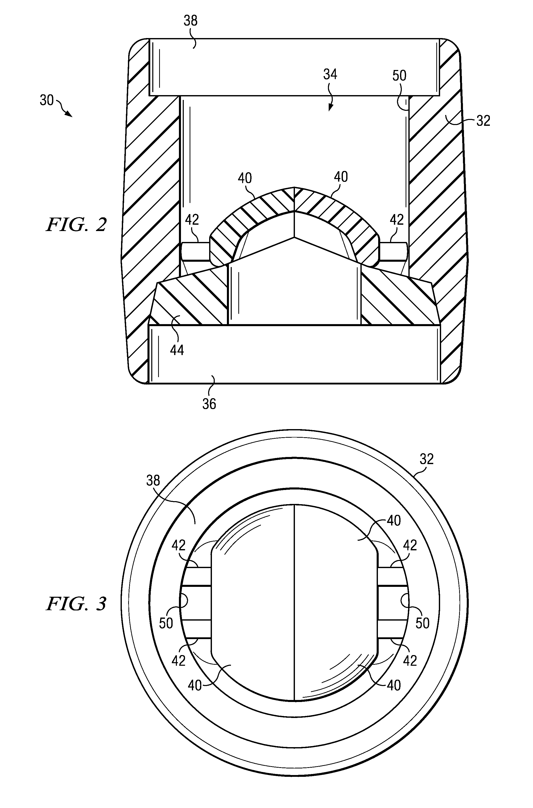
[0027]Referring to the figures, wherein the same reference numerals and symbols are used to refer to equal parts, FIG. 2 shows a valve 30 according to the present invention. The valve includes a housing 32 adapted for connection to the pump chamber of a ventricular assist device (not shown). The housing 32 defines a passage 34, normally cylindrical in configuration, for flowing blood in and out of the VAD. With respect to the valve shown in FIG. 2, the blood would flow upward from an inlet port 36 to an outlet port 38. The valving function is provided by two symmetrical flaps 40 that are attached to the interior surface of the housing 32 by means of struts 42. A support ring 44 provides a base with an interior opening 46 (seen in FIG. 5) and a conforming seat 48 (also seen in FIG. 5) where the flaps 40 rest when the valve is closed.

[0028]For ease of description, the terms up and down are used with reference to the figures in describing the function of the valve 30, it being understo...


PUM


Abstract

A ventricular-assist-device valve includes two flaps hinged to a peripheral wall by means of a couple of flexible struts. As each flap opens and closes during each cycle of operation, the struts flex and open passages for flow around them, around the flaps, and between the struts and the flaps, so as to prevent the formation of dead zones that contribute to the accumulation and deterioration of blood cells that produce clotting. The struts are tensioned so as to exert a pressure against the flow of the blood stream when the flaps are open. This tension creates a pressure differential between the underside and the peripheral regions of the flaps that forces blood flow around the hinges and washes out stagnant cells. As a result, clotting is materially reduced.

Description

BACKGROUND OF THE INVENTION[0001]1. Field of the Invention[0002]The invention relates generally to artificial heart pumps and, in particular, to an improved valve for reducing thrombus in ventricular assist devices.[0003]2. Description of the Prior Art[0004]The heart is the muscle that drives the cardiovascular system in living beings. Acting as a pump, the heart moves blood throughout the body to provide oxygen, nutrients, hormones, and to remove waste products. The blood follows two separate pathways in the human body, the so-called pulmonary and systemic circulatory circuits. In the pulmonary circuit, the heart pumps blood first to the lungs to release carbon dioxide and bind oxygen, and then back to the heart. Thus, oxygenated blood is constantly being supplied to the heart. In the systemic circuit, the longer of the two, the heart pumps oxygenated blood through the rest of the body to supply oxygen and remove carbon dioxide, the byproduct of metabolic functions carried out thro...

Claims


Application Information

Patent Timeline
Patent Type & Authority Applications(United States)
IPC IPC(8): A61M1/10F16K1/18A61M60/178A61M60/268A61M60/892
CPCA61M1/1098A61M1/10A61M60/896A61M60/178A61M60/268A61M60/892
Inventor HUTZENLAUB, JENSGAUL, MICHAEL
Owner SILICON VALLEY BANK
Why Eureka
Try Eureka