
Electronic device for a mechanical blocking.

a technology of electronic device and mechanical block, which is applied in the field of electromechanical locking engagement devices, can solve the problems of increasing the size of the device, affecting the operation of the device, so as to save energy in the electromechanical locking process and reduce power consumption

Inactive Publication Date: 2011-11-17
NUNUPAROV MARTYN SERGEEVICH
View PDF0 Cites 39 Cited by
  • Summary
  • Abstract
  • Description
  • Claims
  • Application Information

AI Technical Summary

Benefits of technology

The aim of the present invention is to provide a compact electronic device for a mechanical blocking with low power consumption for a wide range of applications and in particular, for the locking system with electronically controlled user access. An important condition for saving the energy in the electromechanical locking device is a need to release control element of fixing means from the other load elements in fixing means at least at the moment when control element is forced by an actuator. To make it happen, the moment of said release (unload) of control element should concurs with the moment when electronic unit sends commands to move actuator.
Despite the simplicity of the claimed device, it allows to build a wide variety of automation devices on its basis.

Problems solved by technology

Devices that use solenoids with longitudinally spring-loaded control element are unreliable against the vibrations or shocks along the axis of the solenoid.
These vibrations and shocks can lead to unlocking of the device.
Also, actuators and their electronic control units are often located at the stationary body of the device [see For example, U.S. Pat. No. 4,807,454, 1989 Feb. 28], which leads to an increase of the device sizes or complicates the user interface.
In particular, the plungers in such devices have relatively few degrees of freedom, which limit the options for the application of known technical solutions.

Method used


Image

  • Electronic device for a mechanical blocking.
  • Electronic device for a mechanical blocking.
  • Electronic device for a mechanical blocking.

Examples


Embodiment Construction

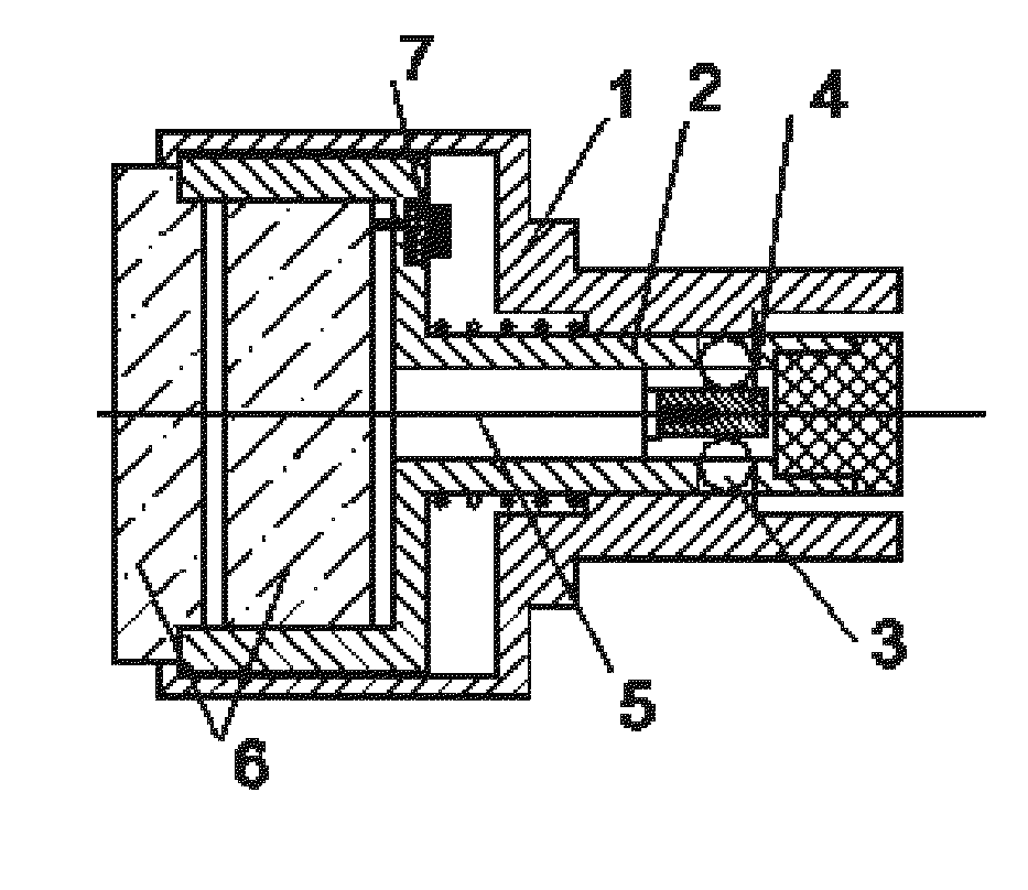
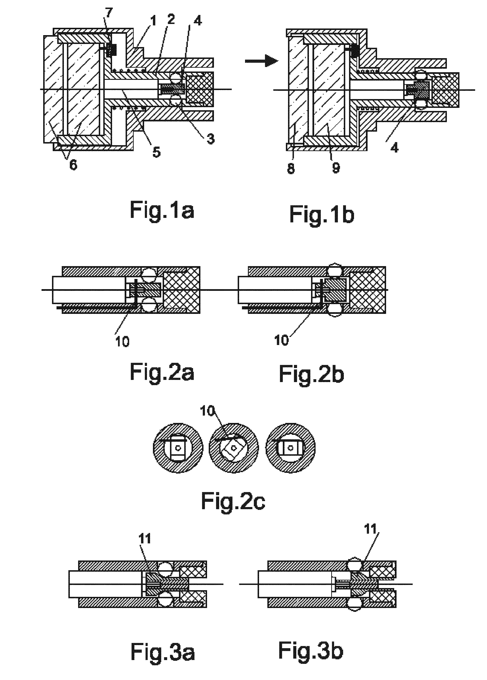
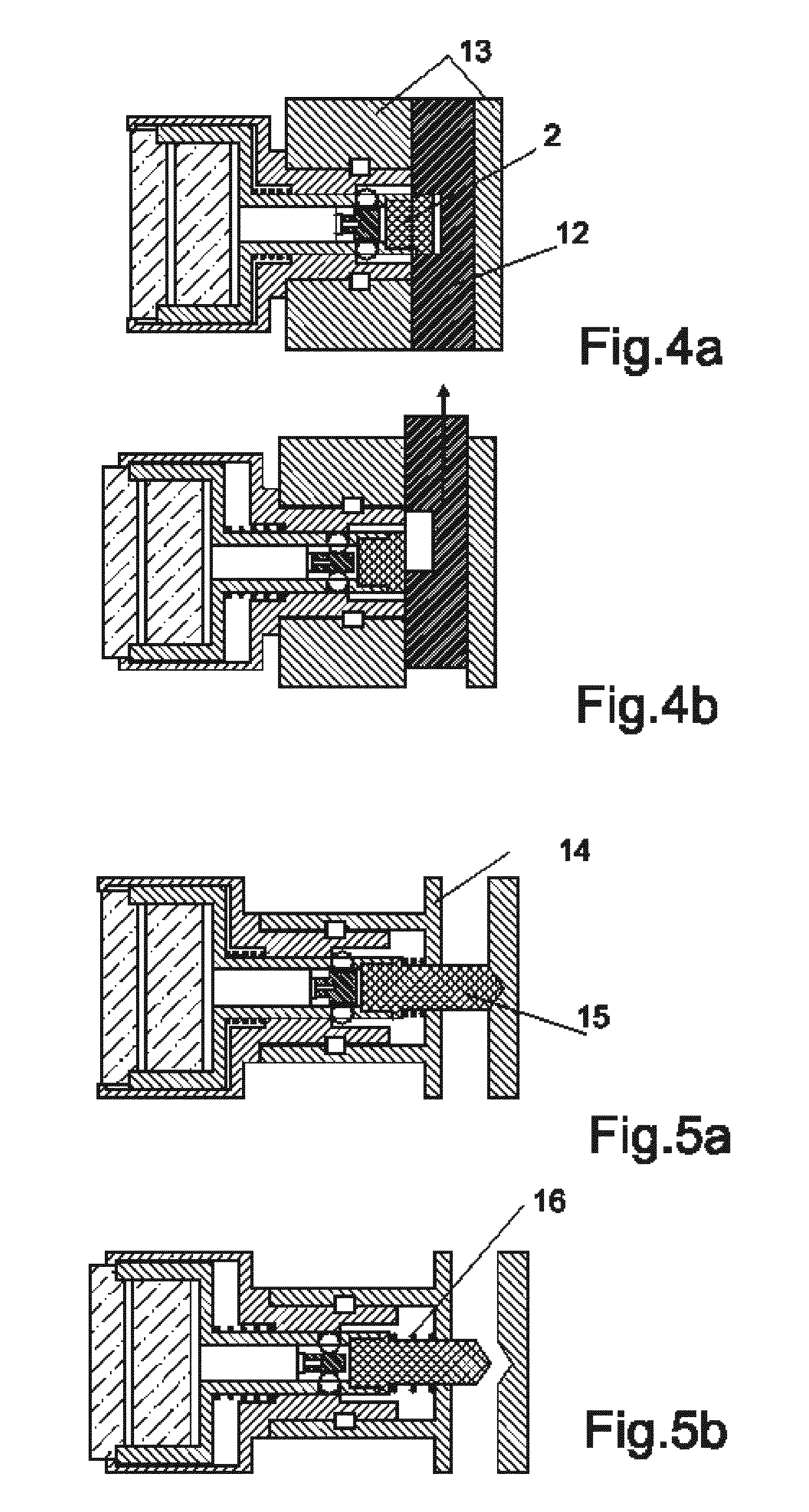
According to present invention, the electromechanical blocking device (see FIG. 1a,b) comprises a body 1, a blocking means mounted in the body 1 with ability for rotation and longitudinal movement. Fixing means 3 mounted in the movable blocking means 2 and designed as for blocking of movement at fixed position of movable blocking means 2 in the body 1. Actuator 5 is also mounted in the blocking means 2, designed to mechanically control the position of control element 4, which is kinematically associated with the elements (balls or rollers) of fixing means 3. Control element 4 can be moved by actuator 5 between two fixed and stable positions.

Actuator 5 is managed by the commands from the electronic unit 6 which is electrically connected to the actuator 5 and if necessary, also placed in the blocking means 2. In order to synchronize moment of switching of actuator 5 the electronic sensor 7, placed into device, which allows to determine the moment of kinematic release (unload) of contr...


PUM


Abstract

An electronic device for a mechanical blocking and power mechanisms on its basis, intended for use in electronic locks, hydraulic / pneumatic automation, electronically controlled valve(tap), electronically controlled power electrical switches and commutators, electro-mechanical clutches and couplings, etc. The devices based on invention are compact, have a simple design and are rather reliable in conditions of shocks and vibrations. Low electric power consumption and corresponding long battery life have been obtained at the prototypes of these devices. It will be effectively used in the systems of autonomous access control.

Description

FIELD OF TECHNOLOGYThe present invention relates to electromechanics and more specifically to the devices for electromechanical locking engagement, electronically controlled motion transfer mechanisms or assemblies. It can be also be used as an independent unit in appliances, instruments and automation systems for various applications. The preferential use of the invention in a devices, such as the electronic locks or other security locking mechanism, where electronic control is associated with the need to control user access rights. Also, the invention will be effective for use in blocking electrical, pneumatic and hydraulic devices, electronic couplings, clutches, etc.PRIOR ARTVarious mechanical devices for blocking, gearing and motion transmission in which the plunger movement is fixed in the body by means of the ball joint [see for example, patents RU2184284, 2002 Jun. 27; RU2295621, 2007 Mar. 20; RU2304247, 2007 Aug. 10; U.S. Pat. No. 5,141,355, 1992 Aug. 25] are known from the...

Claims


Application Information

Patent Timeline
IPC IPC(8): E05B47/02E05B47/00
CPCE05B17/2011E05B47/06E05B47/026Y10T70/7062Y10T70/7057
Inventor NUNUPAROV, MARTYN SERGEEVICH
Owner NUNUPAROV MARTYN SERGEEVICH
Learn More