Pressure balancing device

Active Publication Date: 2011-11-17
SONDEX WIRELINE
View PDF14 Cites 3 Cited by
  • Summary
  • Abstract
  • Description
  • Claims
  • Application Information

AI Technical Summary

Benefits of technology

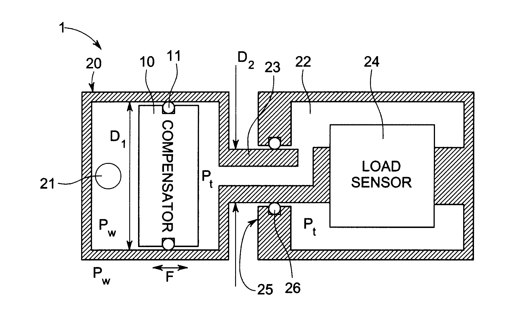
[0009]In accordance with an alternate embodiment of the present invention, a downhole load measuring tool comprising a pressure balancing device is provided. The pressure balancing device comprises: a pressure transmission device having a cross-sectional area and arranged, in use, to be exposed to a fluid; and a fluid chamber having a hollow shaft, the fluid chamber being arranged to be acted on by the pressure transmission device; wherein the cross-sectional area of the hollow shaft is less than the cross-sectional area of the pressure transmission device.
[0016]The area ratio of the piston and the mandrel around the shaft have a ratio smaller than 1, such as less than 0.8 or less then 0.7, for example rather than equal to 1. This reduces the effect of the compensator / pressure transmission device friction / stiffness on the measured variable.
[0004]Downhole logging tools are frequently designed to be pressure balanced. This is where a measurement sensor is located within the body of the tool and is protected from well fluid by appropriate sealed housings, but where some form of pressure transmission device is used to compress a fluid within the tool to approximately the same pressure as the well fluid outside. In this manner, the sensor is exposed to the well pressure, without suffering the consequences of being immersed directly in the well fluid. The compensating mechanism must also allow for the internal fluid to expand at low pressure but high temperature.
[0018]Increased accuracy makes the use of the device in a downhole tool such as a downhole load measuring tool significantly more attractive to users as they can more confidently measure the load being exerted on the toolstring and predict when the cable head will reach breaking point. Balancing the load between the wireline and tractor during deviated well operations, can also be controlled more successfully.

Problems solved by technology

Each mechanism has advantages and disadvantages in terms of the resulting pressure difference between the inside and outside of the tool, such as maintainability, cost, durability and resistance to attack from the chemicals in the well.
However, inherent in the design of a piston compensating system is the need for dynamic sliding seals, which experience high hydrostatic pressures and therefore suffer from high friction, and resist the motion of the piston.
In cases where the sensor inside the tool needs to be at the same pressure as the well fluid for accurate measurement, this differential pressure results in measurement error and is undesirable.

Method used


Image

  • Pressure balancing device
  • Pressure balancing device
  • Pressure balancing device

Examples


Embodiment Construction

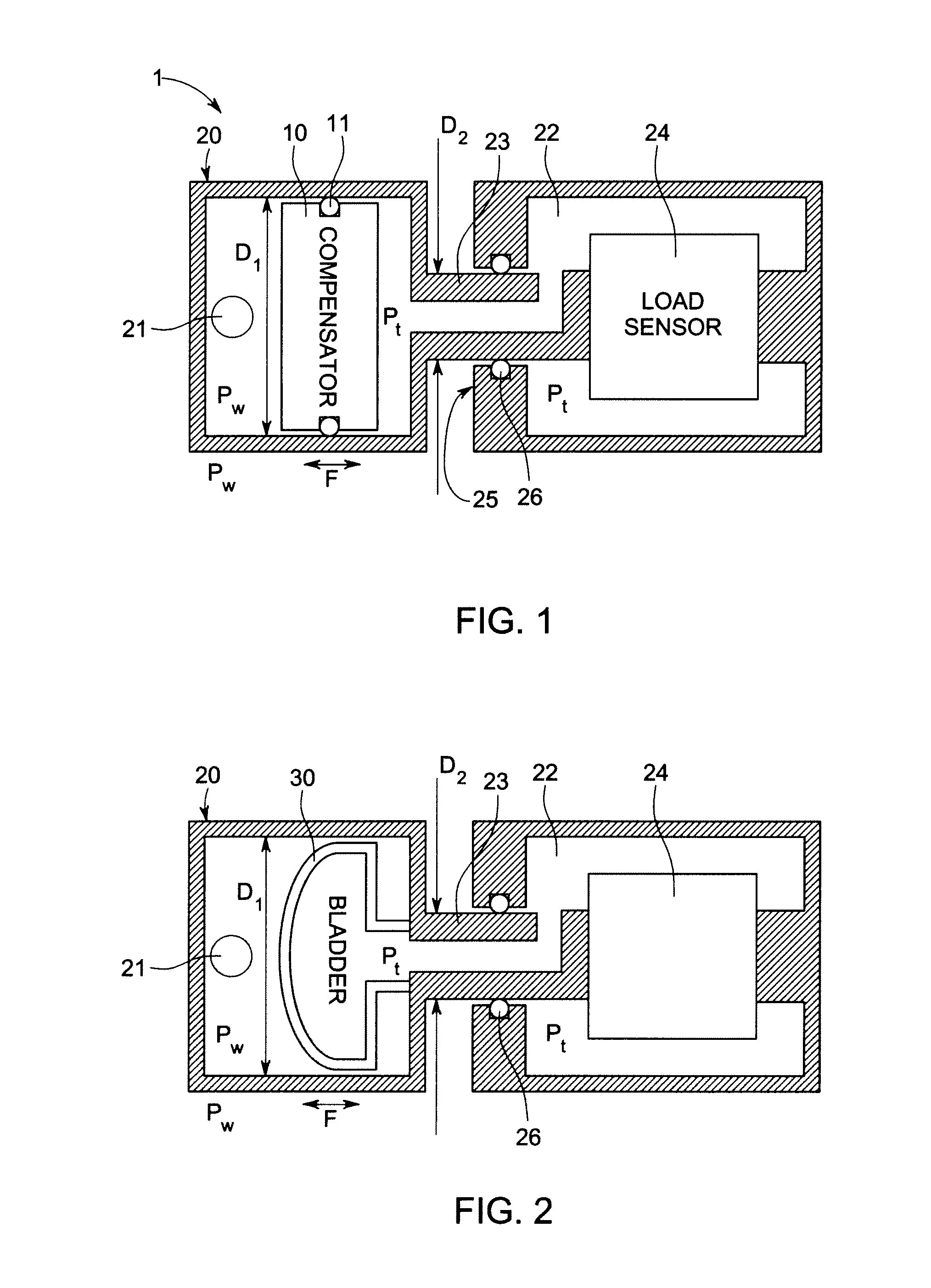
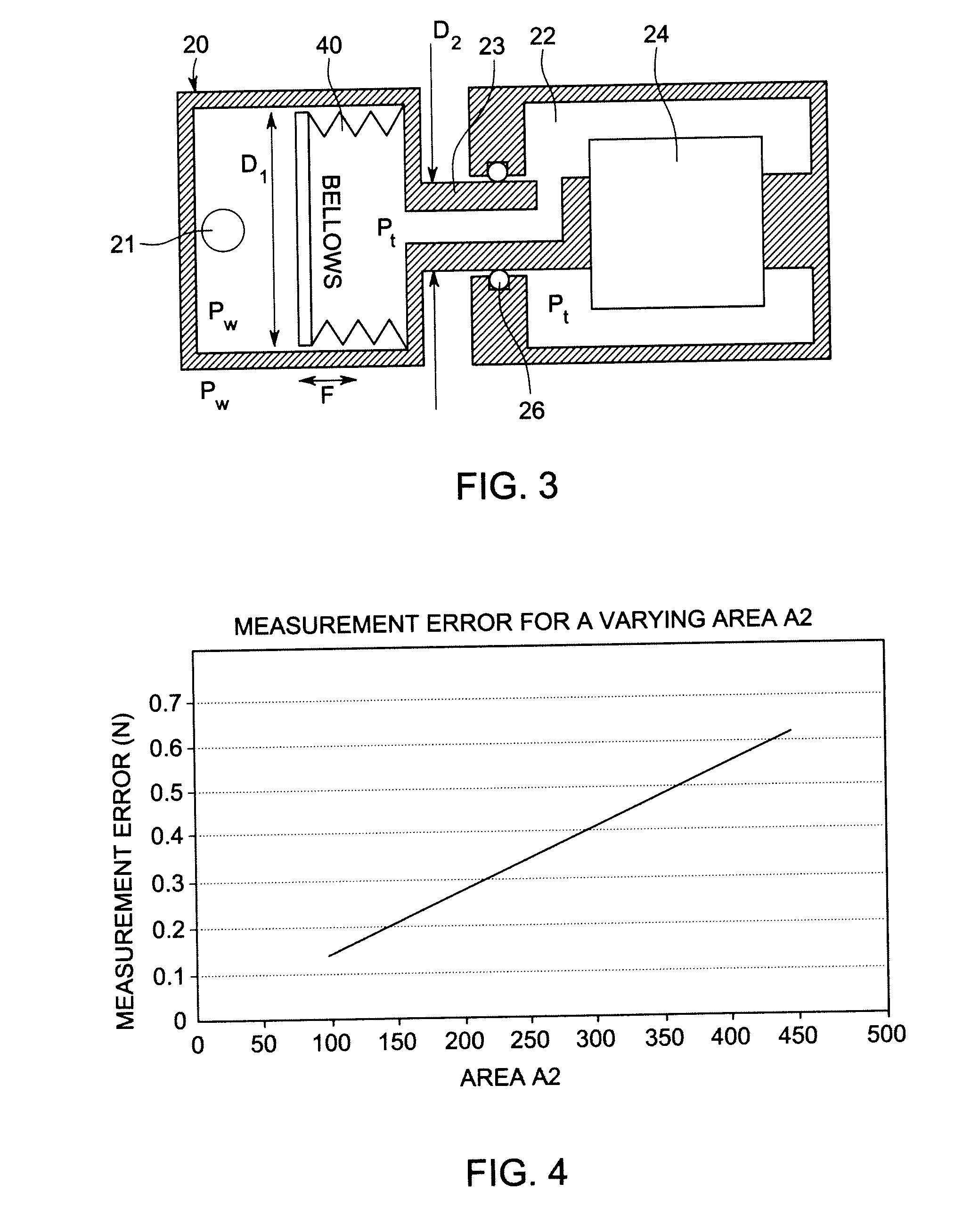
[0015]The embodiments of the present invention provide an improved downhole tool pressure balancing method for transducers, which is sensitive to differential pressure between an oil well for example and the tool interior. Using established pressure balancing mechanisms such as pistons, flexible bellows and rubber bladders, the area ratio of the compensation device and a shaft passing through a mandrel is carefully controlled so as to reduce the impact of differential pressure created by compensator friction or stiffness on the induced transducer error. The hollow shaft may be a load transmission shaft which may be connected to a load sensor.

[0016]The area ratio of the piston and the mandrel around the shaft have a ratio smaller than 1, such as less than 0.8 or less then 0.7, for example rather than equal to 1. This reduces the effect of the compensator / pressure transmission device friction / stiffness on the measured variable.

[0017]The improved pressure balancing configuration allows...


PUM


Abstract

A pressure balancing device for a transducer is provided. The pressure balancing device comprises: a pressure transmission device having a cross-sectional area and arranged, in use, to be exposed to a fluid; and a fluid chamber having a hollow shaft, the fluid chamber being arranged to be acted on by the pressure transmission device; wherein the cross-sectional area of the hollow shaft is less than the cross-sectional area of the pressure transmission device.

Description

BACKGROUND OF THE INVENTION[0001]1. Field of the Invention[0002]Embodiments of the present invention relate to a pressure balancing device, such as for a transducer.[0003]2. Description of the Prior Art[0004]Downhole logging tools are frequently designed to be pressure balanced. This is where a measurement sensor is located within the body of the tool and is protected from well fluid by appropriate sealed housings, but where some form of pressure transmission device is used to compress a fluid within the tool to approximately the same pressure as the well fluid outside. In this manner, the sensor is exposed to the well pressure, without suffering the consequences of being immersed directly in the well fluid. The compensating mechanism must also allow for the internal fluid to expand at low pressure but high temperature.[0005]Pressure compensating mechanisms regularly used downhole include pistons, rubber bladders and flexible metal bellows. Each mechanism has advantages and disadvan...

Claims


Application Information

Patent Timeline
IPC IPC(8): E21B47/06F15B15/04E21B47/00E21B47/01
CPCE21B47/0006E21B47/06E21B47/011G01L19/0645E21B47/007E21B47/017E21B47/01
Inventor RATCLIFFE, JAMES DAVIDBROOM, NICHOLAS PETERGILL, TIMOTHY MICHAEL
Owner SONDEX WIRELINE
Why Eureka
Try Eureka