Heat dissipation device which is pre-built with an air vent structure

a technology of air vents and heat dissipation devices, which is applied in the direction of basic electric elements, semiconductor devices, lighting and heating apparatus, etc., can solve the problems of low cost of dissipation devices, slow heat conduction rate, and low operation speed, and achieve the effect of beautiful appearan

Inactive Publication Date: 2011-11-17
NENG TYI PRECISION INDS
View PDF0 Cites 15 Cited by
  • Summary
  • Abstract
  • Description
  • Claims
  • Application Information

AI Technical Summary

Benefits of technology

[0009]Still another object of the present invention is to form a variation of shapes integrally, allowing the heat dissipation device to have a beautiful appearance.

Problems solved by technology

However, for the conventional heat dissipation device, a base plate of a radiator is installed with cooling fins, and the base plate is tightly pressed on the electronic heating element, to dissipate heat energy from high temperature created when the electronic element is operating, through the cooling fins.
Although this kind of heat dissipation device has a low cost, its heat conduction rate is slow, and hence is only suitable for a computer with a lower operation speed.
As the heat dissipation effect is limited for the electronic heating element requiring to operate with a fast speed or for a long time, the conventional heat dissipation device is not perfect at all.
Nevertheless, as end surfaces of the cold air inlets and the hot air outlets are all vertical to a plane, a wind-break wall will be formed to block the air flow from the fan when the cold air blows in; therefore, it is easy to result in a stagnant layer, such that a heat source will be accumulated between the cooling fins and the fan, thereby wasting power of the fan, and allowing the heat dissipation effect to only work for a normal application.
However, in order to increase wind pressure, rotation of the fan will result in louder noise, and thereby troubling people.
However, as all kinds of elements are having different specifications, they are often unable to be emplaced or are often in conflict with the radiator in assembling, due to the incompatibility with the specification of radiator.
Therefore, other suitable heat dissipation device should be searched for, which usually forms the biggest trouble and an issue to be overcome mostly, upon assembling the radiator.

Method used


Image

  • Heat dissipation device which is pre-built with an air vent structure
  • Heat dissipation device which is pre-built with an air vent structure
  • Heat dissipation device which is pre-built with an air vent structure

Examples


Embodiment Construction

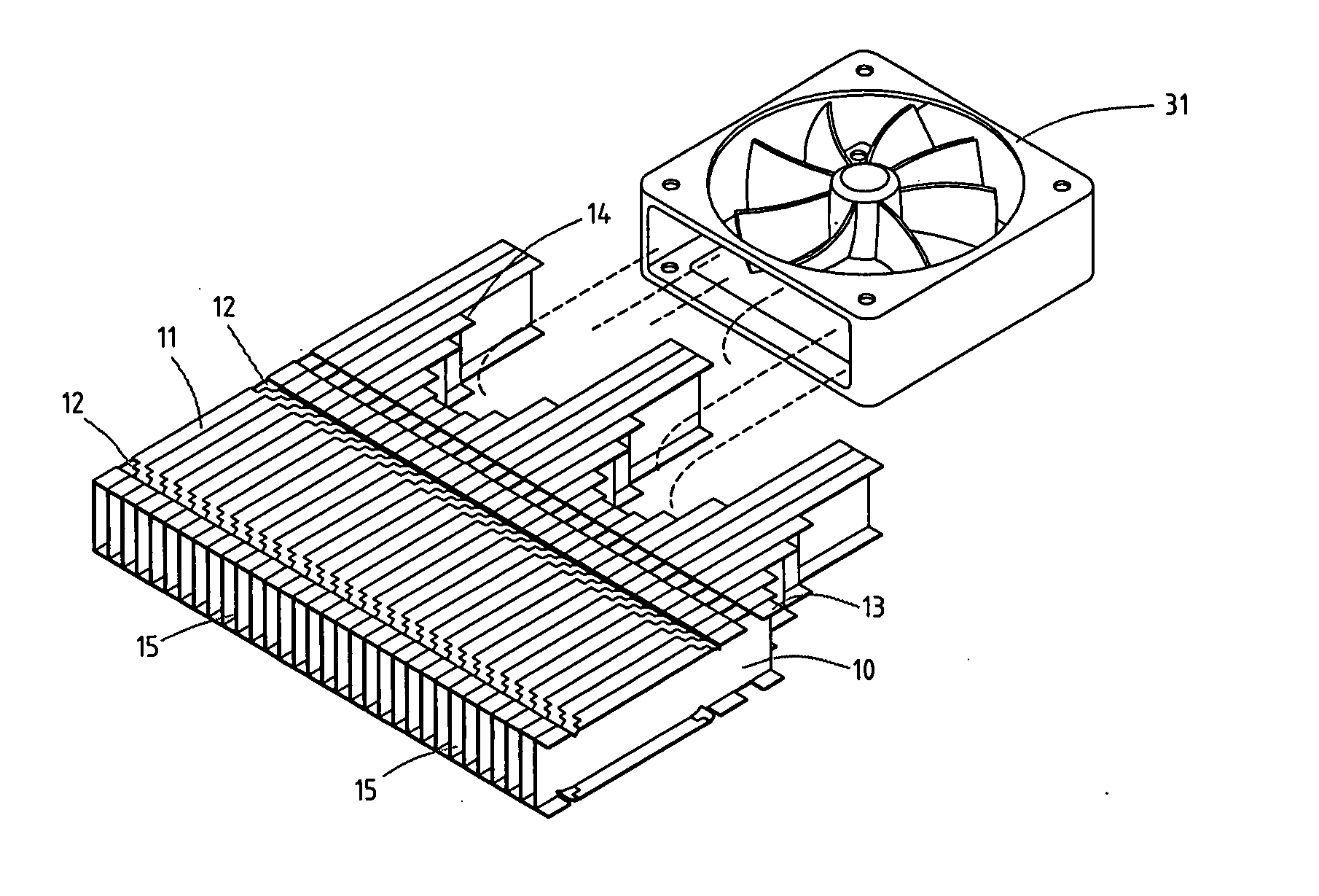
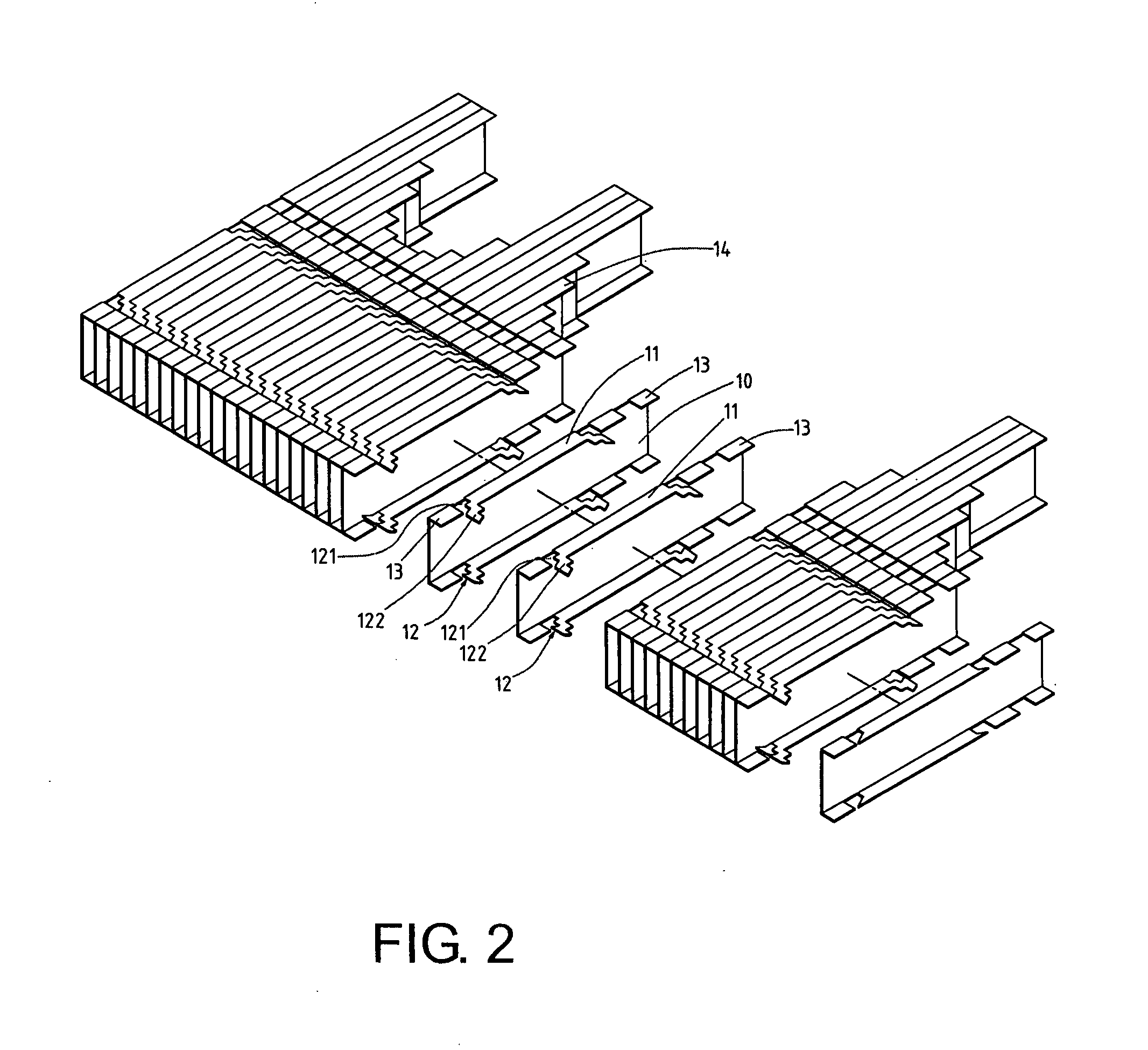
[0019]Referring to FIG. 2, it shows an exploded view of a preferred embodiment of the present invention, wherein a cooling fin 10 is a thin plate formed by punching, a top and bottom rim of the cooling fin 10 are bended horizontally with heat transmission wings 11, and each heat transmission wing 11 is provided with a locking part 12 constituted by a locking slot 121 and a locking hook 122, with the locking slot 121 being extended forward with the locking hook 122. A bended part of the locking hook 122 is formed with an inverted hook, such that the cooling fins 10 can be assembled forward and backward into a cooling fin set, without dropping off. When the cooling fins 10 are formed by punching, a length of each piece can be configured in advance, meaning that upon punching, a fin of different length can be formed by extending respectively from a left and right side of the locking part 12, allowing each cooling fin 10 to be formed with an extension section 13 of different length. Aft...


PUM


Abstract

A heat dissipation device which is pre-built with an air vent structure uses primarily a plurality of cooling fins, which are formed into different lengths, to assemble into the heat dissipation devices of different shapes, for shunning away from other elements inside a computer host. In addition, diversion baffles of a different angle can be arranged and assembled, so as to form air ducts following an angle of wind direction, allowing an air flow to be smoothly guided in by a fan, and to quickly flow into a heat transmission zone in a gap between the cooling fins, such that a heat source can be dissipated more quickly.

Description

BACKGROUND OF THE INVENTION[0001]a) Field of the Invention[0002]The present invention relates to a heat dissipation device which is pre-built with an air vent structure, and more particularly to a heat dissipation device which is formed with all kinds of shapes by assembling cooling fins that are shaped in advance with different lengths, so as to avoid other structures and to form diversion baffles as air ducts for guiding an cold air flow.[0003]b) Description of the Prior Art[0004]To solve an over-heat problem of elements inside a computer host, usually a heat dissipation device is installed on an electronic heating element, such that heat generated from the electronic element can be dissipated by the heat dissipation device. However, for the conventional heat dissipation device, a base plate of a radiator is installed with cooling fins, and the base plate is tightly pressed on the electronic heating element, to dissipate heat energy from high temperature created when the electroni...

Claims


Application Information

Patent Timeline
Patent Type & Authority Applications(United States)
IPC IPC(8): F28F13/00
CPCH01L23/467H01L2924/0002H01L2924/00
Inventor CHANG, TANG-KUEI
Owner NENG TYI PRECISION INDS
Why Eureka
Try Eureka