Keyboard device

a keyboard and keyboard technology, applied in the direction of switches, electrical devices, legends, etc., to achieve the effect of reducing the volume of the keyboard device, and reducing the cost of the mechanism

Inactive Publication Date: 2011-11-17
GLOBAL LIGHTING TECHNOLOGIES INC
View PDF6 Cites 10 Cited by
  • Summary
  • Abstract
  • Description
  • Claims
  • Application Information

AI Technical Summary

Benefits of technology

[0030]By changing the disposing of the light guide element, the present invention not only reduces the volume of the keyboard device but also reduces the cost of mechanism, thus

Problems solved by technology

However, the illuminant keyboard must provide an accommodating space for accommodating the illuminant module so as to increase th

Method used


Image

  • Keyboard device
  • Keyboard device
  • Keyboard device

Examples


first embodiment

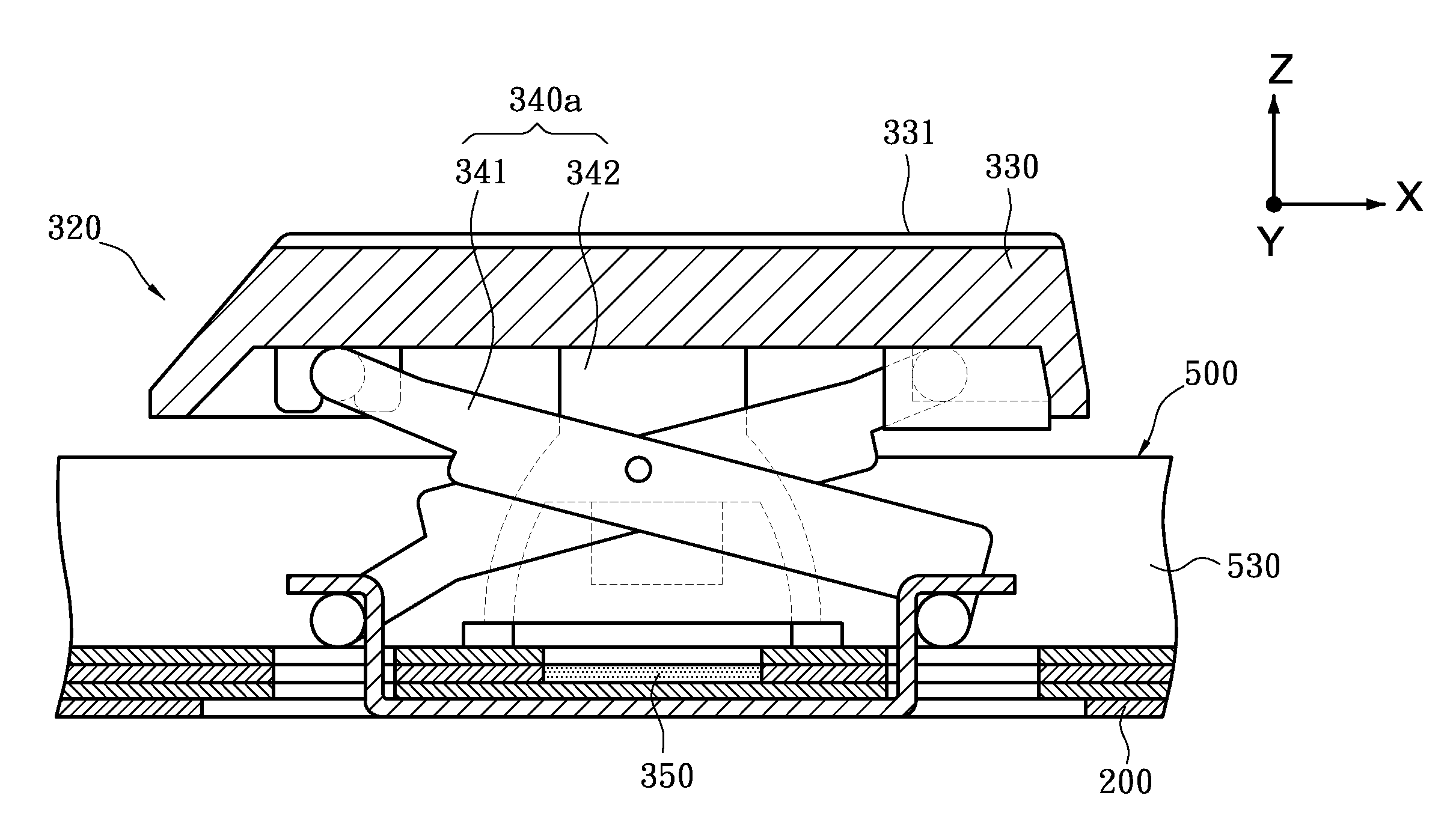
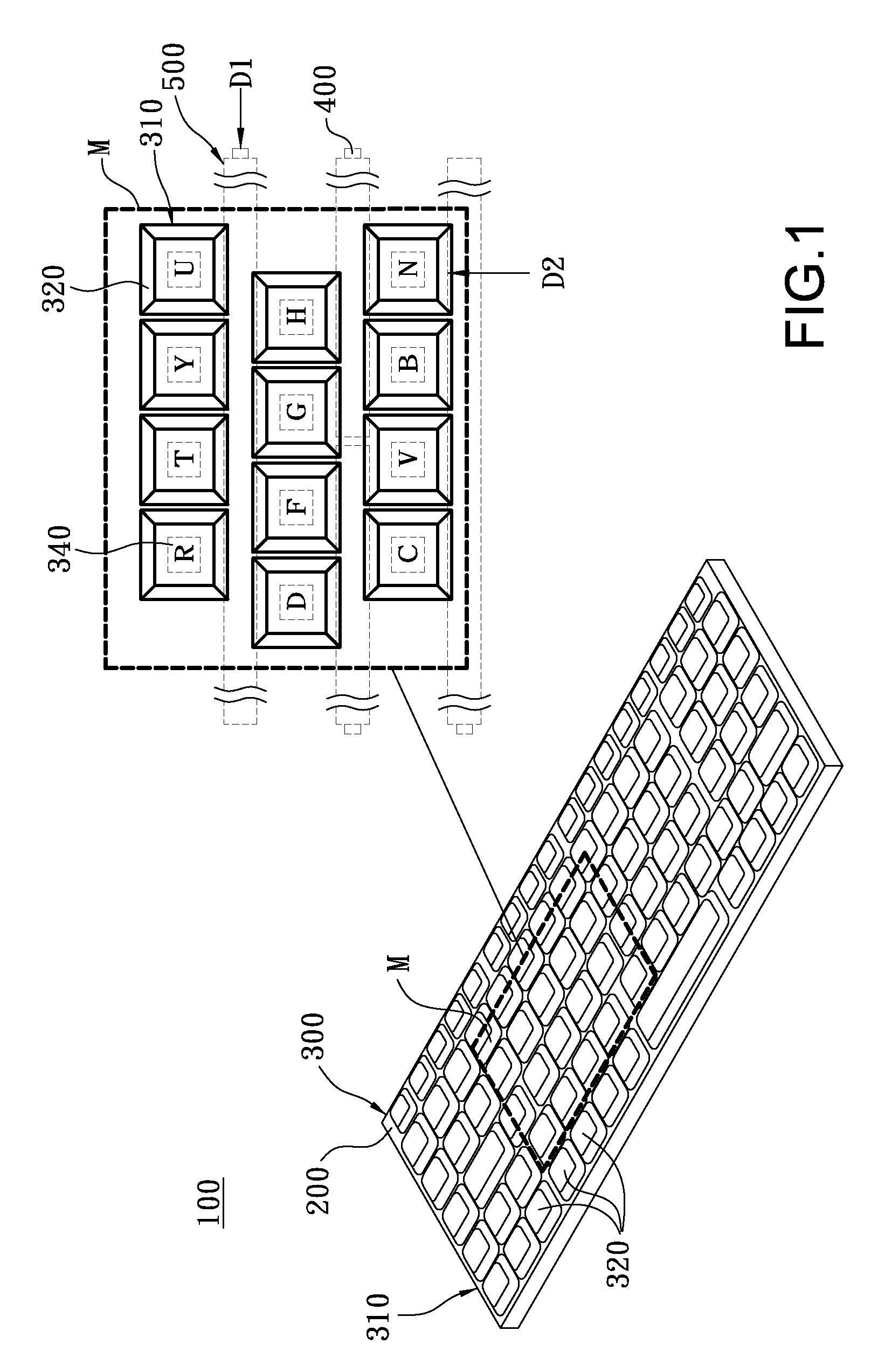
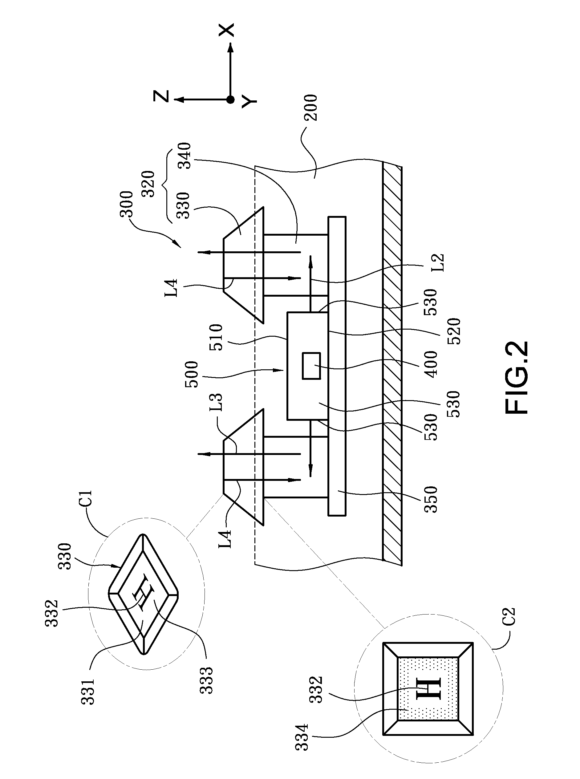
[0051]Referenced is made to FIG. 1 and FIG. 2, FIG. 1 is a schematic view and partially enlarged view of an M area of a keyboard device according to the present invention, FIG. 2 is a partially cross sectional view taken along D1 direction shown in the FIG. 1 of the keyboard device and partially enlarged views of a front surface C1 and a back surface C2 of a keycap according to the present invention. The keyboard device 100 includes a casing 200, a keyboard module 300, a plurality of illuminant elements 400 and a plurality of light guide elements 500 (as shown in the M area of the FIG. 1).

[0052]The casing 200 is used for accommodating the keyboard module 300, the illuminant elements 400 and the light guide elements 500. The casing 200 can be a shell of a keyboard device 100 or a frame for supporting the keyboard module 100.

[0053]The keyboard module 300 is located within the casing 200 and includes a triggering circuit 350 and a plurality of key strings 310 spaced from each other. On...

second embodiment

[0059]Referenced is made to FIG. 4A, which is a partially cross sectional view taken along D1 direction shown in the FIG. 1 of the keyboard device according to the

[0060]In this embodiment, the light guide element 500 is of plate shape (namely, the light guide element 500 is a light guide plate). The light guide element 500 includes two opposite first surfaces 510 and a second surface 520. Not only the first surface 510 but the second surface 520 has a light-emitting part. The two light-emitting parts are facing the recovering components 340 located between two sides of the light guide element 500. One of the third surfaces 530 connected to the first surface 510 and the second surface 520 has a light-incident part faced the illuminant element 400.

[0061]In this embodiment, a light guide element 500 is disposed between each two of the keyboard string 310. The illuminant element 400 is a light emitting diode and disposed at an extreme of a light guide element 500 (as the upper light gui...

third embodiment

[0065]Referenced is made to FIG. 4B, which is a partially cross sectional view taken along D1 direction shown in the FIG. 1 of the keyboard device according to The light guide element 501 is of circular cylinder shape, such as light guide cylinder. The light guide element 501 includes an outer circumference surface 550 and two circular end-surfaces 560. Each circular end-surface 560 is disposed on two terminal of the light guide element 501 and has a light-incident part. The outer circumference surface 550 surrounds the circular end-surfaces 560 and has a light-emitting part.

[0066]In the various examples for the keyboard device 100 of the present invention mentioned above, each illuminant element 400 generates light L1 (shown in FIG. 3) emitted to the light-incident part of light guide element 501 along a third axial direction (such as Y axis) and the light-emitting part of the light guide element 501 emits light L2 to the recovering component 340 along a second axial direction (su...


PUM


Abstract

A keyboard device includes at least an illuminant element, at least a pressing key element and a light guide element. The pressing key element includes a keycap reciprocating along a first axial direction when being pressed and a recovering component attached to the keycap for supporting and pushing back the keycap when not pressed. The light guide element is located at one side of the recovering component. The light guide element includes at least a light-incident part and a light-emitting part. The light-incident part is used for receiving light emitted from the illuminant element. The light-emitting part emits light along a second axial direction to the recovering component so that the recovering components guide light to the keycap, wherein the second axial direction is different to the first axial direction.

Description

BACKGROUND OF THE INVENTION[0001]1. Field of the Invention[0002]The present invention related to a keyboard device, and more particularly to an illuminated keyboard device.[0003]2. Description of Prior Art[0004]In order to overcome the problem that uses do not identify the keyboard or use keyboard in the low brightness or darkness environment, many species of illuminated keyboards are disclosure for using in the keyboard device using in desk top computers, laptop computers, notebook computers or network computers. The illuminated keyboards are all had an illuminant module which is embedded for emitting light to each of the key so that users can clearly identify the symbol of each keycaps and the striking locations.[0005]In general, illuminant module of the illuminant keyboard is located under the keyboard for providing light to illuminate the keys of the keyboard.[0006]However, the illuminant keyboard must provide an accommodating space for accommodating the illuminant module so as ...

Claims


Application Information

Patent Timeline
IPC IPC(8): H01H13/70H01H13/02
CPCH01H13/83H01H2219/044H01H2227/00H01H2219/062H01H2225/00H01H2219/06
Inventor LEE, SHIN-KUNLIU, HUANG-CHUNCHUNG, SHENG-JULIN, YU-JENGTSAI, CHUNG-LIN
Owner GLOBAL LIGHTING TECHNOLOGIES INC
Why Eureka
Try Eureka