
Solar fuel cell

a fuel cell and solar energy technology, applied in the direction of energy input, metal/metal-oxide/metal-hydroxide catalyst, physical/chemical process catalyst, etc., can solve the problem of not being thermodynamically favorable at standard temperature and pressure to decompose water reaction

Active Publication Date: 2011-11-17
HONDA MOTOR CO LTD
View PDF21 Cites 10 Cited by
  • Summary
  • Abstract
  • Description
  • Claims
  • Application Information

AI Technical Summary

Problems solved by technology

The decomposition of water reaction is not thermodynamically favorable at standard temperature and pressure.

Method used


Image

  • Solar fuel cell
  • Solar fuel cell

Examples


Embodiment Construction

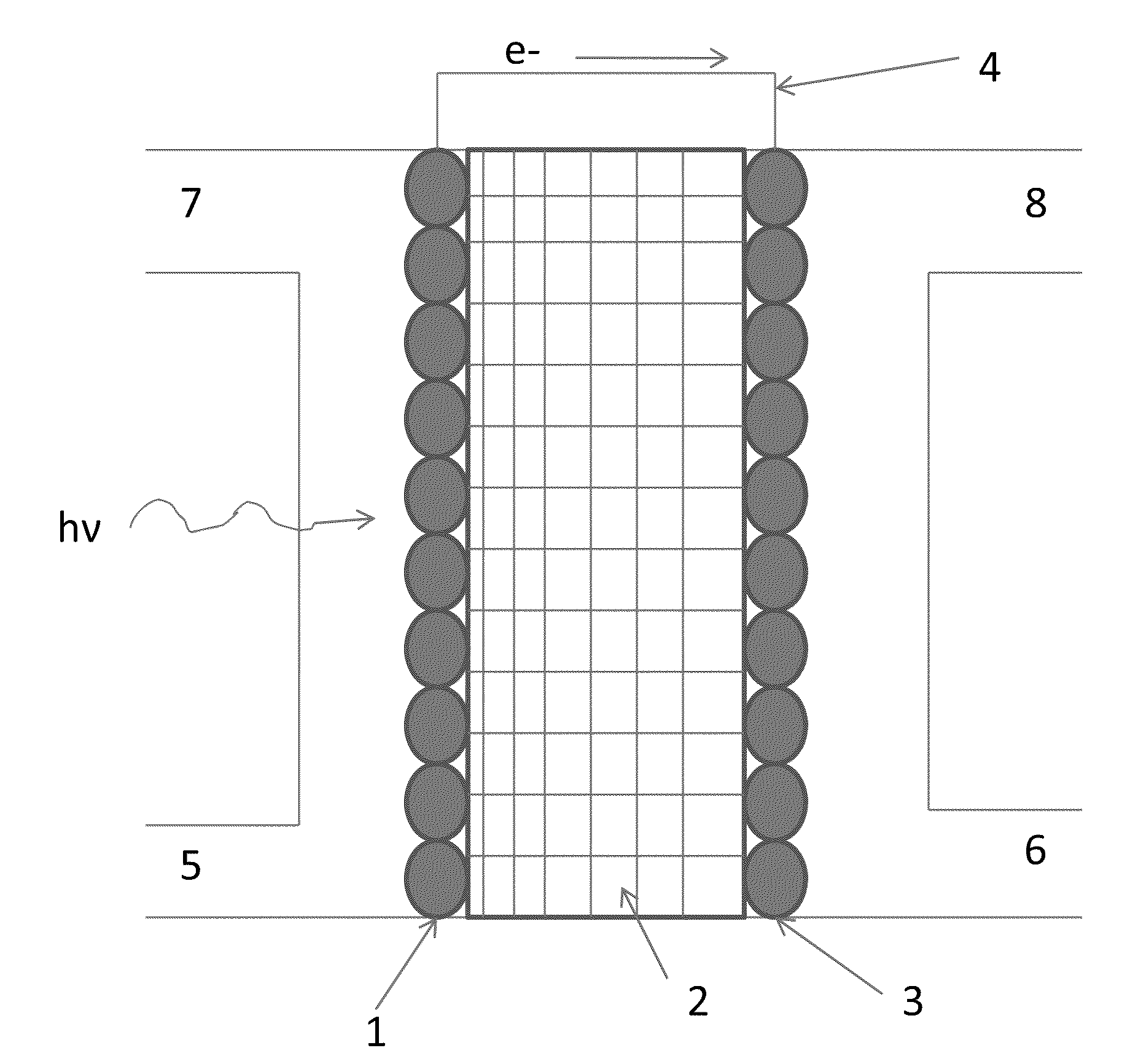
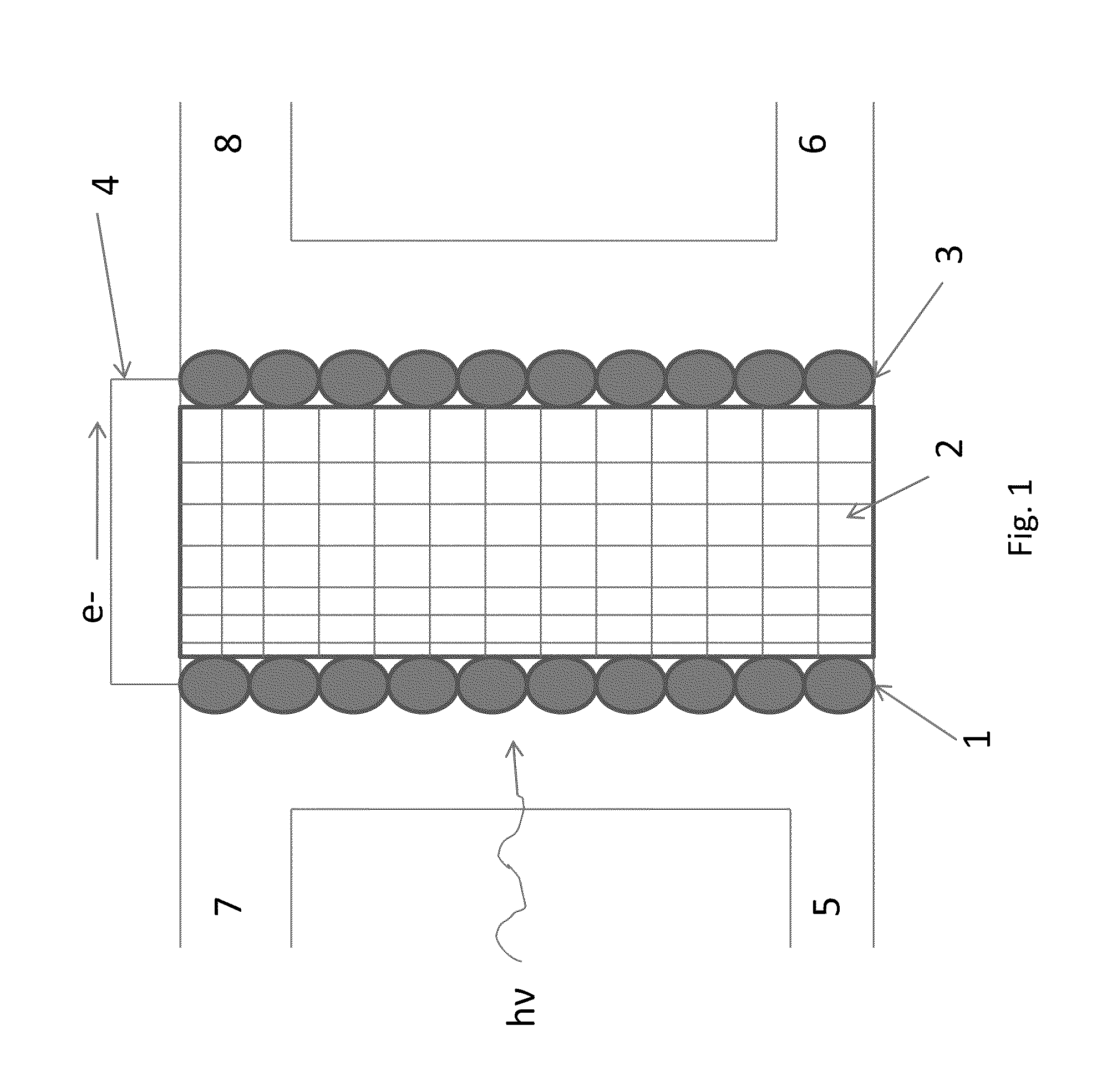
The present disclosure is directed to a process for converting a carbon-containing component and water to a hydrocarbon component by first providing a light-harvesting, charge-separating and transporting component, a proton-conducting membrane, and a catalyst component. An electrical connection between the light-harvesting, charge-separating and transporting component and the catalyst component is also provided. The light-harvesting, charge-separating and transporting component is exposed to radiation of a sufficient wavelength to produce separated electron and hole pairs.

Water is contacted with the electron and hole pairs to produce, via oxidation, oxygen gas, protons, and electrons. The oxygen gas is removed from the process, while the electrons are transported through the electrical connection from the light-harvesting, charge-separating and transporting component to the catalyst component, and the protons are conducted across the proton-conducting membrane to contact the catalys...


PUM

PropertyMeasurementUnit
Electric potential / voltageaaaaaaaaaa
Band gapaaaaaaaaaa
Electrical conductoraaaaaaaaaa

Abstract

The present teachings are directed to a method of converting water and a carbon-containing compound, such as CO2, into a hydrocarbon through a process of absorbing sunlight on a light-absorbing component to photoelectrochemically oxidize water and reacting the products from that water oxidation reaction over a catalyst with the carbon-containing compound to produce the desired hydrocarbon compound.

Description

BACKGROUND1. Field of the InventionThe present teachings relate to a method of converting water and a carbon-containing compound into a hydrocarbon through a process of absorbing sunlight on a light-absorbing component to photoelectrochemically oxidize water and reacting the products from that water oxidation reaction over a catalyst with a carbon-containing compound, such as CO2, to produce a hydrocarbon compound.2. Discussion of the Related ArtPhotosynthesis is a kinetically slow process for the production of hydrocarbons from CO2 and water using solar radiation as an energy source to drive the conversion reaction.The well-known Fischer-Tropsch synthesis process of producing hydrocarbons from CO and water requires high temperatures and pressures, even in the presence of a catalyst, to produce hydrocarbons.Several techniques are known to facilitate the oxidative decomposition of water into hydrogen and oxygen gases. The decomposition of water reaction is not thermodynamically favor...

Claims


Application Information

Patent Timeline
IPC IPC(8): C25B3/00C25B9/08C25B3/25C25B9/19
CPCB01J19/127B01J19/2475B01J23/38C25B1/003B01J35/065B01J2219/0884B01J2219/0892B01J35/004C07C1/02C07C29/15C07C45/49C25B1/55Y02P20/133B01J35/39B01J35/59C25B9/19C25B3/03
Inventor HE, TING
Owner HONDA MOTOR CO LTD
Learn More