

Dielectric materials for power transfer system
a technology of dielectric materials and power transfer systems, applied in the direction of inductances, alkaline earth titanates, inorganic chemistry, etc., can solve the problems of sensitive load and gap variations of resonance induction
- Summary
- Abstract
- Description
- Claims
- Application Information
AI Technical Summary
Problems solved by technology
Method used
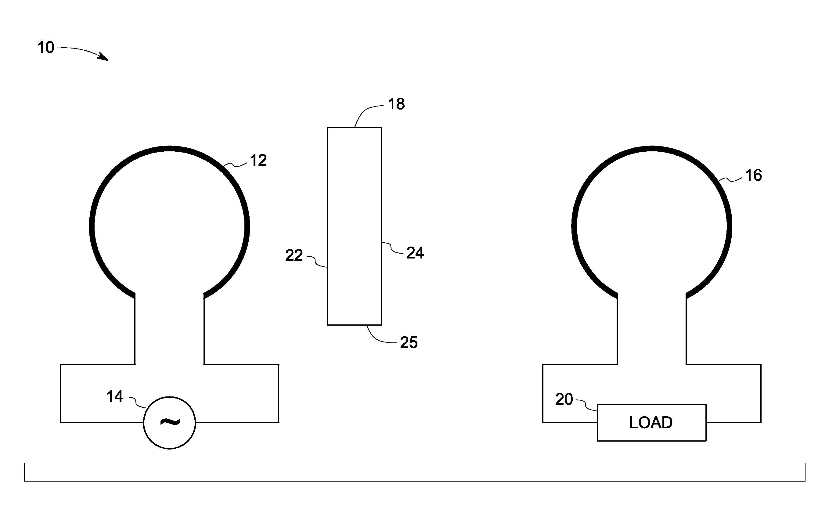
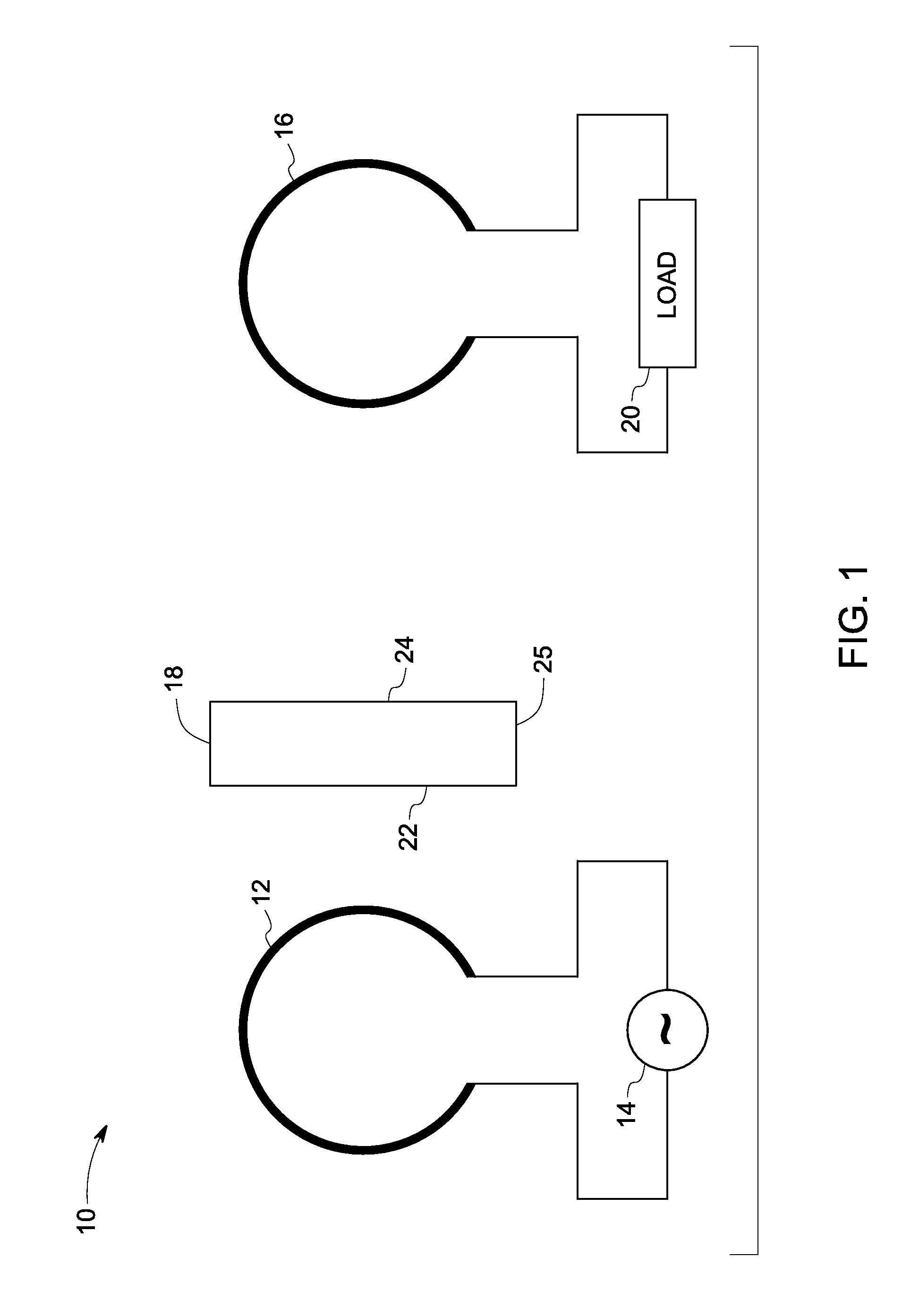
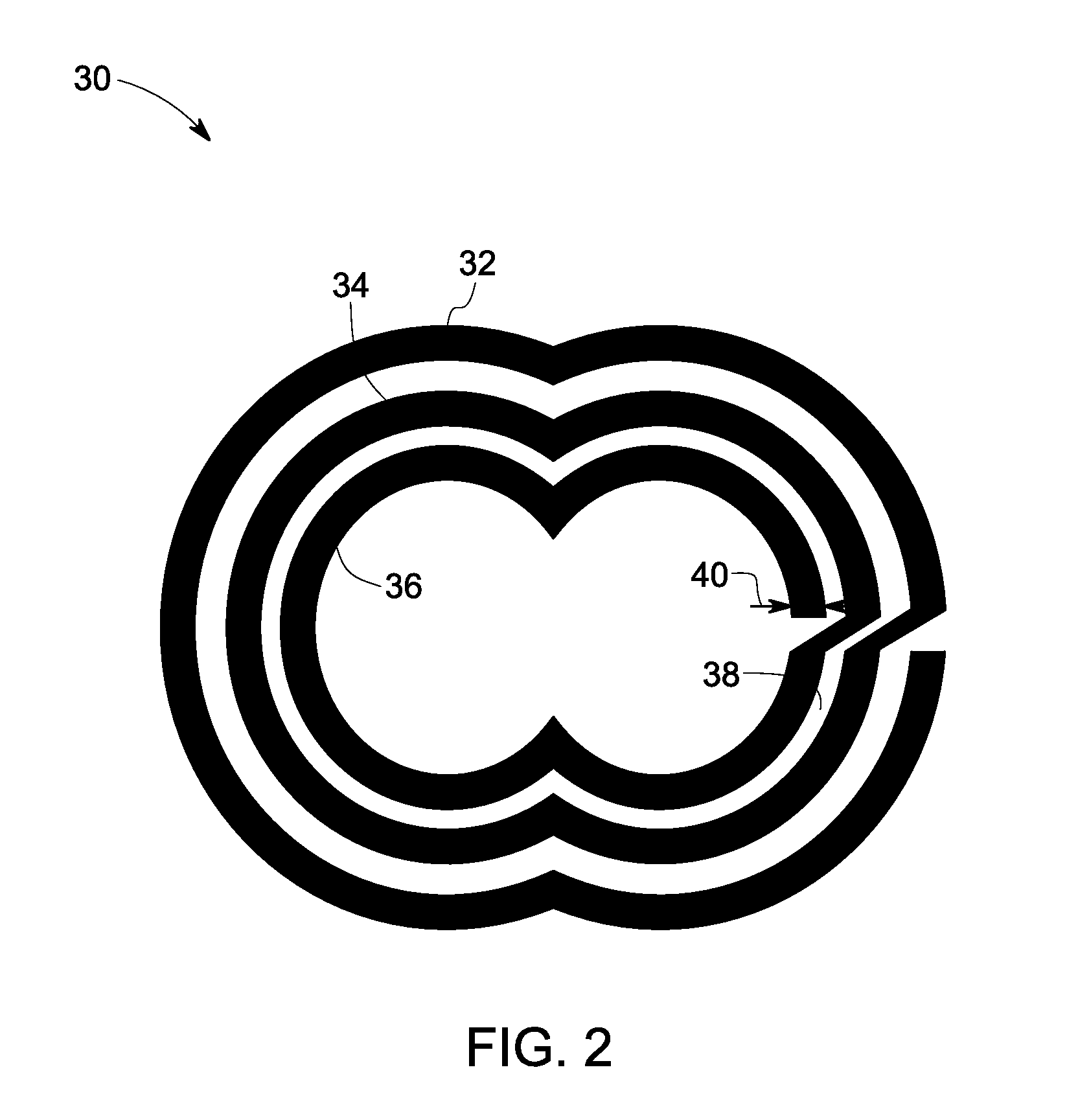
Image

Examples
example 1
Ba0.55Sr0.4Ca0.05TiO3 Processed by CIP
[0078]About 13.071 gm of BaCO3, 9.579 gm of TiO2, 10.152 gm of Sr(NO3)2 and 0.6 gm of CaCO3 were added together and hand mixed using mortar and pestle for 15 minutes. The mixture was added with approximately equal volume of isopropanol and about 3 times by volume of zirconia grinding media and rack-milled for around 6 hours. The homogeneous mixture was transferred to an alumina crucible and calcined at 1100° C. for 2 hrs. About 2 wt % of PVA was added and mixed to the calcined powder using an agate mortar. Equal volume of isopropanol was added to the resultant material and rack-milled again.
[0079]The powder was then pressed into pellets of about 3 gram weight using hydraulic pressing with a pressure of about 4 MPa. The pellets were vacuum sealed in polyethylene film and cold isostatically pressed with about 30 MPa pressure. The pellets were sintered at 1440° C. for 2 hours in air. A silver paste coating of a few microns thickness was applied to ...
example 2
Ba0.01Sr0.2Ca0.79Cu3Ti4O12
[0080]About 0.079 gm of BaCO3, 12.790 gm of TiO2, 1.175 gm of SrCO3, 3.165 gm of CaCO3 and 9.554 gm of CuO were added together and hand mixed using mortar and pestle for 15 minutes. The mixture was added with approximately equal volume of isopropanol and about 3 times by volume of zirconia grinding media and rack-milled for around 6 hours. The homogeneous mixture was transferred to an alumina crucible and calcined at 1000° C. for 24 hrs. About 2 wt % of PVA was added and mixed to the calcined powder using an agate mortar. Equal volume of isopropanol was added to the resultant material and rack-milled again.
[0081]The powder was then pressed into pellets of about 3 gram weight using hydraulic pressing with a pressure of about 6 MPa. The pellets were sintered at 1100° C. for 2 hours in air. A silver paste coating of a few microns thickness was applied to the sintered pellets and was dried at 200° C. for 2 hours. The dielectric constant and loss tangent of the...
example 3
Ca2Cu2Ti3.94Al0.06O11.97
[0082]About 8.497 CaCO3, 6.753 gm of CuO, 13.357 gm of TiO2 and 0.955 gm of Al(NO3)3.9H2O were added together and hand mixed using mortar and pestle for 15 minutes. The mixture was added with approximately equal volume of isopropanol and about 3 times by volume of zirconia grinding media and rack-milled for around 6 hours. The homogeneous mixture was transferred to an alumina crucible and calcined at 1000° C. for 24 hrs. About 2 wt % of PVA was added and mixed to the calcined powder using an agate mortar. Equal volume of isopropanol was added to the resultant material and rack-milled again.
[0083]The powder was then pressed into pellets of about 3 gram weight using hydraulic pressing with a pressure of about 6 MPa. The pellets were sintered at 1100° C. for 2 hours in air. A silver paste coating of a few microns thickness was applied to the sintered pellets and was dried at 200° C. for 2 hours. The dielectric constant and loss tangent of the pellet was then me...
PUM
| Property | Measurement | Unit |
|---|---|---|
| resonance frequency | aaaaa | aaaaa |
| resonance frequency | aaaaa | aaaaa |
| thickness | aaaaa | aaaaa |
Abstract
Description
Claims
Application Information