Carbonitride based phosphors and light emitting devices using the same

a technology of carbonitride and phosphor, which is applied in the direction of discharge tube luminescent screen, discharge tube/lamp details, luminescent composition, etc., can solve the problems of high thermal stability, difficult to achieve 90% quantum yield at room temperature, and impede the successful application of existing phosphor materials

Inactive Publication Date: 2011-11-17
LIGHTSCAPE MATERIALS
View PDF4 Cites 44 Cited by
  • Summary
  • Abstract
  • Description
  • Claims
  • Application Information

AI Technical Summary

Benefits of technology

[0048]In the description of phosphors, a conventional notation is used, wherein the chemical formula for the host crystal is given first, followed by a colon and the formula for the activator(s) and co-activator(s).

Problems solved by technology

This is a vicious cycle that precludes successful applications of existing phosphor materials.
Successful development of light emitting devices incorporating both phosphors and a light source, such as pcLED lamps for general illumination, therefore requires the development of phosphors that can operate highly efficiently at temperatures of 80° C.-150° C. The risk is that it is difficult both to achieve 90% quantum yield at room temperature and to have high thermal stability at 80° C.-150° C. The thermal stability of a phosphor's luminescence is an intrinsic property of the phosphor which is determined by both the composition and the structure of the crystalline material.
For example, residual carbon that remains after phosphor preparation processes utilizing carbon can hinder the emission intensity of the phosphor.
Further, the dark color of carbide materials naturally predisposes it to absorbing, rather than reflecting, light.
Generically, the network structure formed by Si—C bonds has a strong absorption in the entire visible light spectral region, and therefore has been previously considered not suitable for use in host materials for high efficiency phosphors.
This effect is detrimental to achieving a phosphor having a high emission efficiency.

Method used


Image

  • Carbonitride based phosphors and light emitting devices using the same
  • Carbonitride based phosphors and light emitting devices using the same
  • Carbonitride based phosphors and light emitting devices using the same

Examples


example 1

The Preparation of Phosphors of Formulation (1)

Example 1(a)

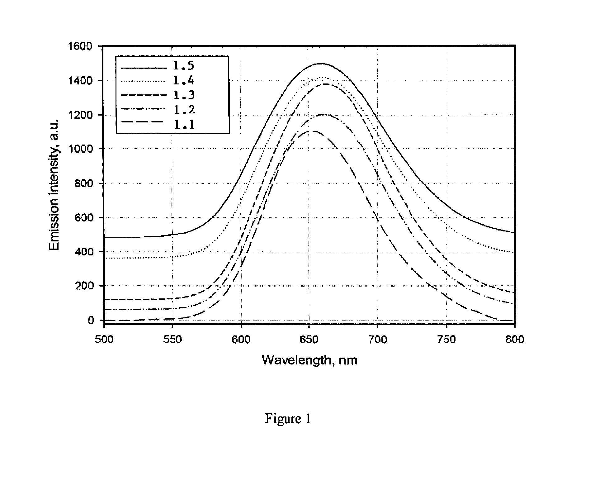
[0103]Powders of Ca3N2, AlN, Si3N4, EuN and SiC were mixed in a designed ratio as listed in Table 1 with a mortar and pestle under the protection of N2 atmosphere. In this series of preparations, the formulation parameter x was fixed at x=0.5 while y was varied from 0 to 0.10. This variation corresponds to an increase of C content and a decrease of the [Al] / [Si] ratio, as seen in Table 1. The mixture was then loaded in a firing boat or crucible and was fired at 1600° C. for 6 hours under N2 / H2 atmosphere. The product powder was then ground and sieved.

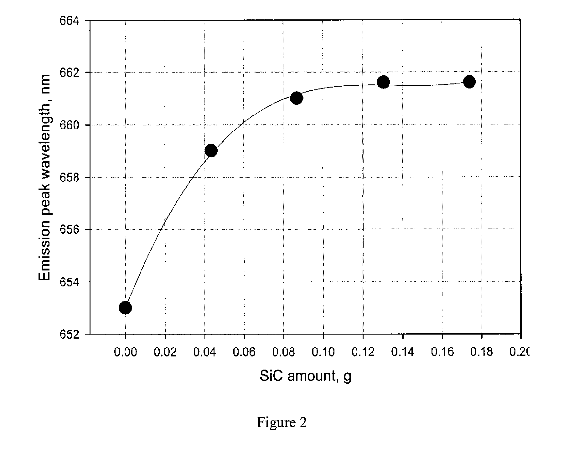
[0104]The product is expressed by the formulation of Ca1-xAlx-xySi1-x+xyN2-x-xyCxy:Eu2+. This phosphor emits a red light under blue or nUV light excitation (FIG. 1). In the samples set forth in Table 1, the SiC of each sample was increased from sample to sample. A preparation (sample ID 1.1) that contains no SiC, i.e. [SiC]=0, was prepared as a reference sample. As depicted in F...

example 1 (

Example 1(b)

[0108]Phosphor samples were prepared according to the process described in Example 1(a) using the starting materials and weights listed in Table 6. The product is expressed by the formulation of Ca1-xAlx-xySi1-x+xyN2-x-xyCxy:Eu2+. In these preparations, the x value was systematically increased from 0.45 to 0.6 and the y value was fixed at 0.05. This change lead to a variation of [Al]3+ / [Si]4+ ratio from about 0.81 to about 1.54 across the preparations. When the carbon content is nearly fixed, the unit cell volume increases as the x value increases (i.e. [Al]3+ / [Si]4+ ratio increases). This is ascribed to the fact that the bond length of Al—N (or Al—C) is longer than that of Si—N (or Si—C), and is demonstrated by the changes of the crystal unit cell parameters shown in Table 8 and FIG. 8 where the lattice parameters a, b, and c of Ca1-xAlx-xySi1-x+xyN2-x-xyCxy:Eu2+ (y=0.05, Eu=1 mol %) increase as the value of x increases. Additionally, from the body color and the fluores...

example 2

The Preparation of Phosphors of Formulation (2)

[0109]Powders of Ca3N2, AlN, BN, Si3N4, EuN, SiC and metal Na were mixed in a designed ratio as set forth in Table 9 with a mortar and pestle under the protection of N2 atmosphere. The mixture was then loaded in a firing boat or crucible and was fired at 1600° C. for 6 hours under N2 / H2 atmosphere. The product powder was then ground and sieved. The product is the formulation of Ca1-x-zNazM(III)x-xy-zSi1-x+xy+zN2-x-xyCxy:Eu, M(III)=(Al, B). This phosphor emits a red light under blue or nUV light excitation (FIG. 9). The emission band width increases with the increase of the added SiC amount (FIG. 10), indicating a carbide effect on the fluorescence properties. The phosphors are excited by a light of wavelength from 350 nm to 610 nm, and more efficiently excited by a light of wavelength from 420 nm to 550 nm (FIG. 11). As depicted in FIG. 12, when the phosphors are excited by a green light, for example, at 550 nm, the emission intensity d...


PUM

PropertyMeasurementUnit
temperaturesaaaaaaaaaa
temperatureaaaaaaaaaa
temperaturesaaaaaaaaaa

Abstract

Disclosed herein is a novel group of carbidonitride phosphors and light emitting devices which utilize these phosphors. In certain embodiments, the present invention is directed to a novel family of carbidonitride-based phosphors expressed as follows:
Ca1-xAlx-xySi1-x+xyN2-x-xyCxy:A  (1);
Ca1-x-zNazM(III)x-xy-zSi1-x+xy+zN2-x-xyCxy:A  (2);
M(II)1-x-zM(I)zM(III)x-xy-zSi1-x+xy+zN2-x-xyCxy:A  (3);
M(II)1-x-zM(I)zM(III)x-xy-zSi1-x+xy+zN2-x-xy-2w/3CxyOw-v/2Hv:A  (4); and
M(II)1-x-zM(I)zM(III)x-xy-zSi1-x+xy+zN2-x-xy-2w/3-v/3CxyOwHv:A  (4a),
wherein 0<x<1, 0<y<1, 0≦z<1, 0≦v<1, 0<w<1, x+z<1, x>xy+z, and 0<x-xy-z<1, M(II) is at least one divalent cation, M(I) is at least one monovalent cation, M(III) is at least one trivalent cation, H is at least one monovalent anion, and A is a luminescence activator doped in the crystal structure.

Description

CLAIM OF PRIORITY[0001]This application claims priority to U.S. Provisional Application No. 61 / 334,967, filed May 14, 2010, and U.S. Provisional Application No. 61 / 354,992, filed Jun. 15, 2010, the disclosures of which are hereby incorporated by reference in their entireties.STATEMENT REGARDING REFERENCES[0002]All patents, publications, and non-patent references referred to herein shall be considered incorporated by reference into this application in their entireties.BACKGROUND OF INVENTION[0003]In recent years, research and development efforts have been intense on developing combinations of light sources and phosphors that will yield useful, high-performing light emitting devices, with the result that both efficient high-power light sources and efficient phosphors have been demonstrated. For example, both light emitting diode (“LED”) chips and phosphors for phosphor-converted LED (“pcLED”) devices have been demonstrated. A unique aspect of some phosphor / light source combinations (s...

Claims


Application Information

Patent Timeline
Patent Type & Authority Applications(United States)
IPC IPC(8): H01J1/63C09K11/59
CPCC04B35/58H01L33/502C04B35/6268C04B2235/3208C04B2235/3229C04B2235/3418C04B2235/3826C04B2235/3852C04B2235/386C04B2235/3865C04B2235/3873C04B2235/3891C04B2235/40C04B2235/445C04B2235/761C09K11/0883C09K11/7721C04B35/584H01L2224/48247H01L2224/8592C09K11/77218C09K11/08C09K11/64C09K11/77H01L33/50
Inventor LI, YUANQIANGTIAN, YONGCHIROMANELLI, MICHAEL DENNIS
Owner LIGHTSCAPE MATERIALS
Why Eureka
Try Eureka