Signal level crossing detector circuit

a detector circuit and signal level technology, applied in the direction of pulse technique, high frequency circuit adaptation, instruments, etc., can solve the problems of increased probability of failure of supply, high power dissipation on the low voltage side and, in particular, on the high voltage side, and the inability to meet the requirements of power dissipation and switching speed,

Inactive Publication Date: 2011-11-17
AVAGO TECH INT SALES PTE LTD
View PDF8 Cites 17 Cited by
  • Summary
  • Abstract
  • Description
  • Claims
  • Application Information

AI Technical Summary

Problems solved by technology

For example, there may be an increased likelihood of failure in supply if there is more than a 2% variation in the phase of a mains supply from a twenty-four hour mean.
A disadvantage of a zero crossing detector including the electrical isolator circuit of FIG. 1 is its high power dissipation on the low voltage side and, in particular, on the high voltage side.
Hence, a zero crossing detector including the electrical isolator circuit of FIG. 1 presents an unacceptable compromise between power dissipation and switching speed.

Method used


Image

  • Signal level crossing detector circuit
  • Signal level crossing detector circuit
  • Signal level crossing detector circuit

Examples


first embodiment

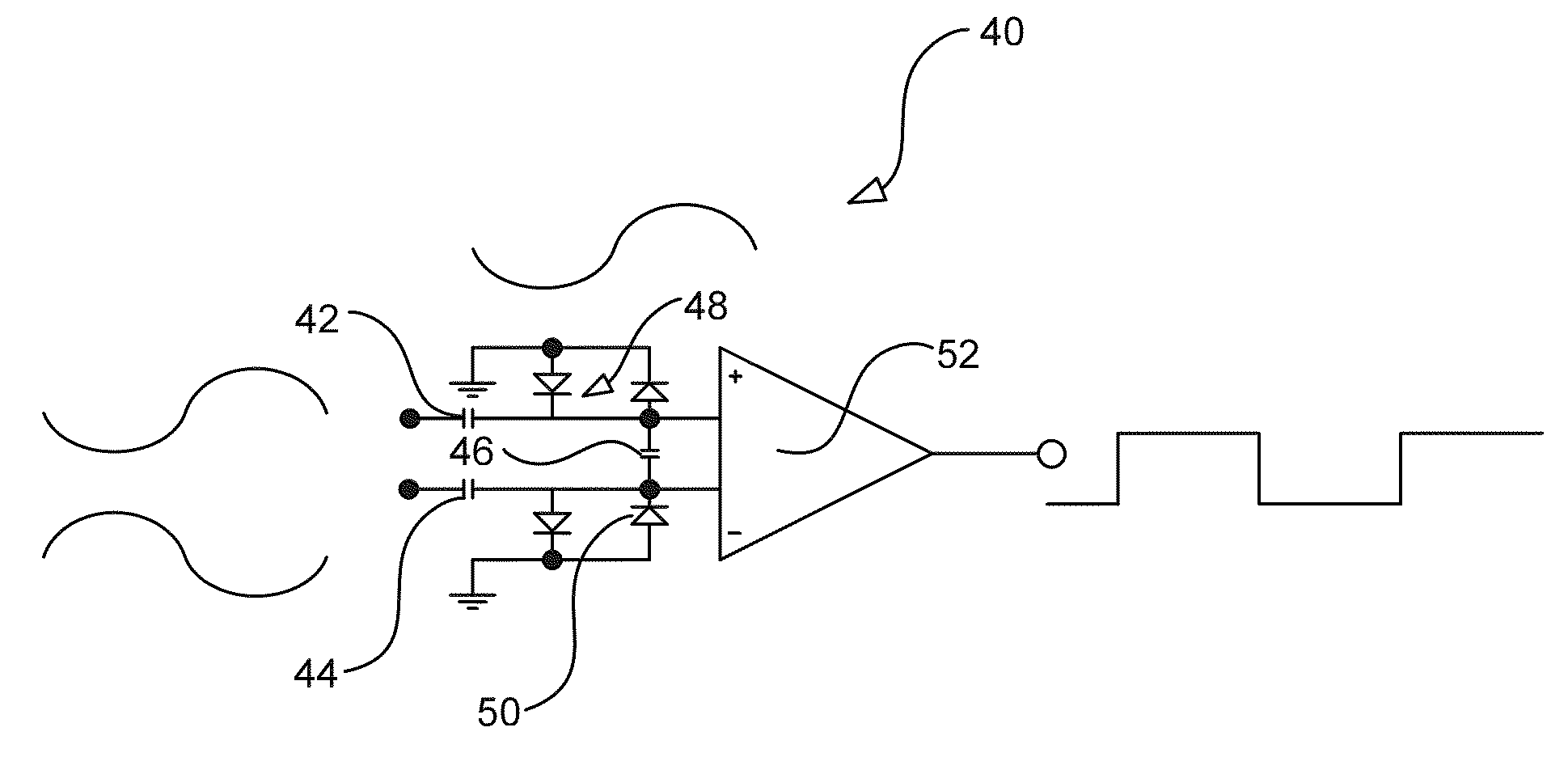
[0042]Referring now to FIG. 3A, a signal level crossing detector circuit 40 is shown. The signal level crossing detector circuit 40 includes first 42, second 44 and third 46 series connected capacitors, a first 48 and a second 50 pair of back to back diodes and a comparator 52. The first and second capacitors 42, 44 constitute a DC isolator. A first plate of the first capacitor 42 constitutes a first input to the DC isolator and a first plate of the second capacitor 44 constitutes a second input to the DC isolator. Although not shown in FIG. 3A, a voltage source operative to provide a domestic mains signal, such as 230 Vrms at 50 Hz or 120 Vrms at 60 Hz, to the first and second inputs. The second plate of the first capacitor 42 is electrically connected to the non-inverting input of the comparator 52 and to a first plate of the third capacitor 46. The second plate of the second capacitor 44 is electrically connected to the inverting input of the comparator 52 and to a second plate o...

fifth embodiment

[0048]FIG. 7 illustrates signal level crossing detector circuit 90. Components in common with the forth embodiment of FIG. 6 are indicated with common reference numerals. The circuit 90 of FIG. 7 is the same as the circuit of FIG. 6 with the following exception. A pair of back to back diodes 48 is connected between the non-inverting input to the comparator 52 and ground. The back to back diodes 48 provide ESD protection on the low voltage side of the DC isolator formed by the first capacitor. Otherwise the circuit of FIG. 7 operates in the same fashion as the circuit of FIG. 6.

[0049]FIG. 8 illustrates plan 160 and cross-section 162 views of one of the first, second or third capacitors of FIG. 3A are shown in FIG. 8. As can be seen, each of the first 164 and second 166 plates of the capacitor are defined by respective metal layers on the top and bottom surfaces of the printed circuit board. The metal layers are disposed such that they share the same footprint and so that the non-cond...


PUM


Abstract

A signal level crossing detector circuit includes a DC isolator and a detector circuit. The DC isolator has at least a first input, which is operable to receive a high voltage AC signal, and at least a first capacitor, a first plate of the first capacitor being electrically connected to the first input. The detector circuit is operable at a low voltage and has at least a first detector input, the first detector input being electrically connected to a second plate of the first capacitor, the low voltage detector circuit being operable to provide a change in output signal in dependence on a high voltage AC signal on the first input crossing a predetermined signal level. The signal level crossing detector may be single ended or differential.

Description

CROSS-REFERENCE TO PRIORITY APPLICATION[0001]This application claims priority under 35 U.S.C. §119(a) to Great Britain Application Serial No. GB 1007892.1 filed May 12, 2010 and to Great Britain Application Serial No. GB 1007896.2 filed May 12, 2010, both of which are incorporated herein by reference in their entirety for all purposes.BACKGROUND OF THE INVENTION[0002]1. Field of the Invention[0003]The present invention relates to a signal level crossing detector circuit for use in particular but not exclusively in mains voltage powered consumer products.[0004]2. Description of the Related Art[0005]Mains voltage powered consumer products, such as multimedia home networking nodes, are required for reasons of safety to have electrical isolation between mains voltage circuitry and low voltage circuitry. Despite the electrical isolation there is often a need to convey signals across the electrical isolation barrier between the mains voltage circuitry and the low voltage circuitry. The de...

Claims


Application Information

Patent Timeline
Patent Type & Authority Applications(United States)
IPC IPC(8): H03L5/00
CPCG01R15/06G01R19/12G01R15/16H05K1/0239H05K1/0256H05K1/162H05K2201/09309H05K2201/09972G01R19/175H03H7/004
Inventor BARNETT, IAINHOLLAND, WILLIAM MICHAEL JAMESHURWITZ, JONATHAN EPHRAIM DAVID
Owner AVAGO TECH INT SALES PTE LTD
Why Eureka
Try Eureka