Optical detection device, display device, and electronic apparatus

a display device and optical detection technology, applied in static indicating devices, distance measurement, instruments, etc., can solve the problems of increasing the size of the system, the difficulty of position detection using the resistance-type touch panel or the capacitance-type touch panel described,

Inactive Publication Date: 2011-11-17
SEIKO EPSON CORP
View PDF6 Cites 14 Cited by
  • Summary
  • Abstract
  • Description
  • Claims
  • Application Information

AI Technical Summary

Benefits of technology

[0012]In such a case, since the first and second emitting light intensity distributions can be formed, for example, by using one light guide, downsizing of the device can be achieved. In addition, since the object can be detected based on the result of the light reception at a time when the first emitting light intensity distribution is formed and the result of the light reception at a time when the second emitting light intensity distribution is formed, a sensing operation can be performed while the effects of external disturbing light such as environmental light are reduced, and accordingly, the detection accuracy can be improved.
[0014]By using two light guides as above, optical design such as adjustment of light emission characteristics can be simplified. In addition, since the object can be detected based on the result of the light reception at a time when the first emitting light intensity distribution is formed and the result of the light reception at a time when the second emitting light intensity distribution is formed, a sensing operation can be performed while the effects of external disturbing light such as environmental light are reduced, and accordingly, the detection accuracy can be improved.
[0022]In such a case, since the effect of external disturbing light at the time of forming the first emitting light intensity distribution and the effect of the external disturbing light at the time of forming the second emitting light intensity distribution can be offset, the detection accuracy can be improved. The light emission control that is performed such that the detected amount of light reception during the first light emission period and the detected amount of light reception during the second light emission period are the same, may be the light emission control that is performed through a reference light source unit.
[0026]In such a case, since the divergence of the emitting light in the direction intersecting the detection area of the object can be suppressed, incorrect detection can be prevented.
[0030]In such a case, since the surface reflection on the first and second slit faces can be suppressed, the divergence of the emitting light can be more effectively suppressed.

Problems solved by technology

Accordingly, in such display devices, it is difficult to realize position detection using the resistance-type touch panel or the capacitance-type touch panel described above.
However, in these position detecting devices, there are problems such as an increase in the size of the system.

Method used


Image

  • Optical detection device, display device, and electronic apparatus
  • Optical detection device, display device, and electronic apparatus
  • Optical detection device, display device, and electronic apparatus

Examples


Embodiment Construction

[0050]Hereinafter, preferred embodiments of the invention will be described in detail. The embodiments described below are not for the purpose of limiting the scope of the invention as defined by the claims. In addition, not all the configurations described in the embodiments are essential prerequisites of the invention.

1. Basic Configuration

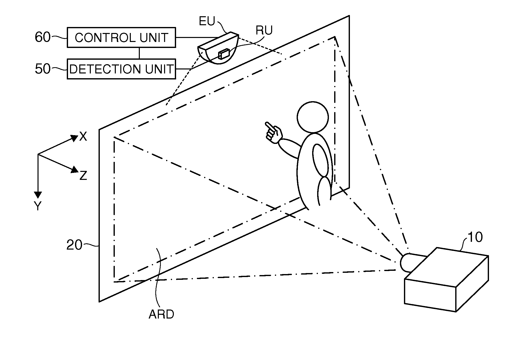
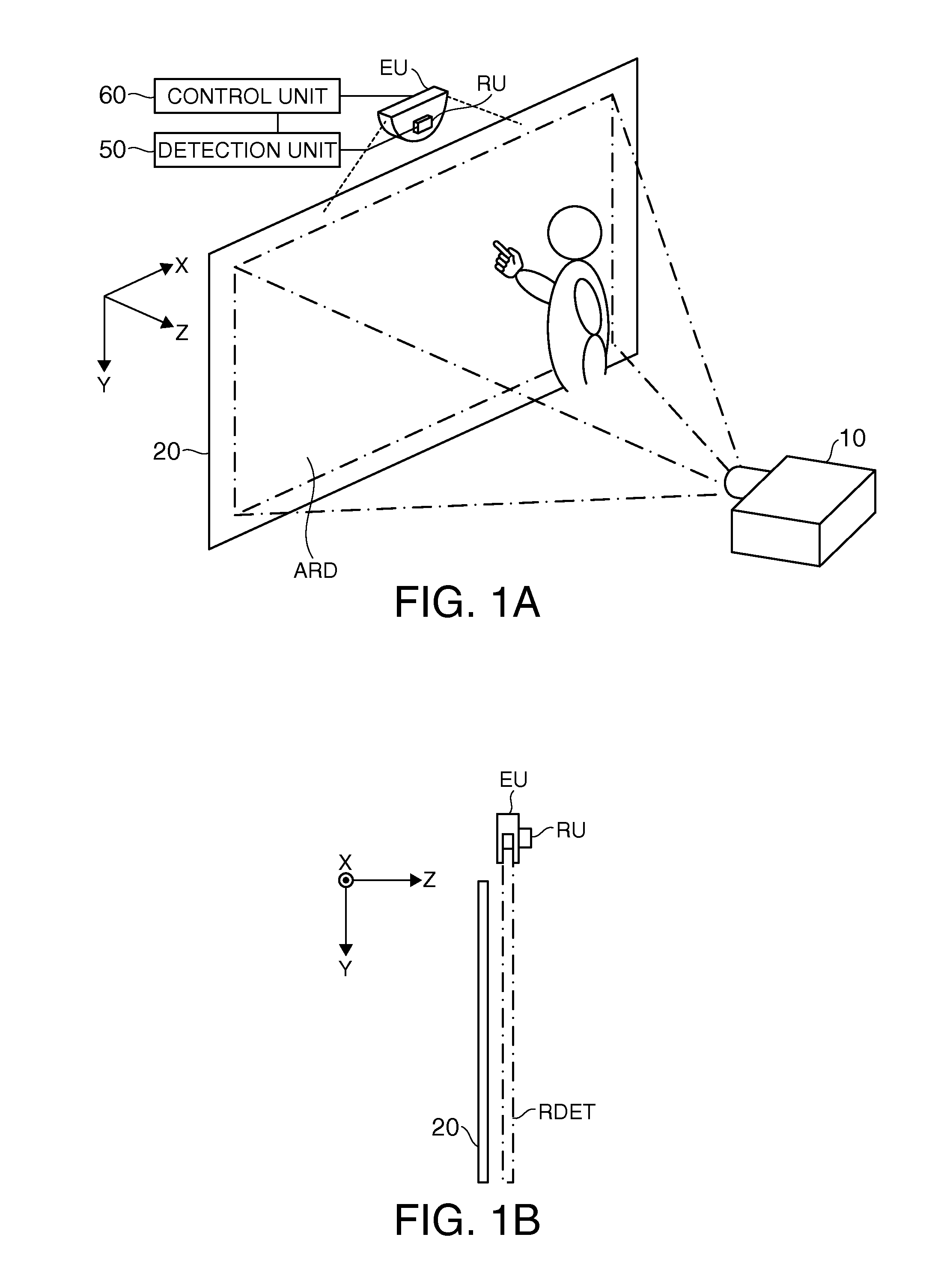
[0051]FIGS. 1A and 1B illustrate an example of the basic configuration of an optical detection device according to a first embodiment and a display device or an electronic apparatus that uses the optical detection device. FIGS. 1A and 1B are examples in which the optical detection device according to this embodiment is applied to a liquid crystal projector or a projection-type display device (projector) known as a digital micro mirror device. In FIGS. 1A and 1B, axes intersecting with one another are set as an X axis, a Y-axis, and a Z-axis (in a broader sense, first, second, and third coordinate axes). To be more specific, the direction of the ...


PUM


Abstract

An optical detection device includes: a light source unit that emits source light; a curve-shaped light guide that includes: a light incident surface to which the source light is incident, the light incident surface being located in an end portion of the light guide; and a convex surface from which the source light received by the light incident surface is output; an emitting direction setting unit that receives the source light output from the convex surface of the light guide and sets an emitting direction of emitting light to a direction of a normal line of the convex surface; a light receiving unit that receives reflection light acquired by reflecting the emitting light off an object; and a detection unit that detects at least a direction in which the object is located based on the light reception in the light receiving unit.

Description

[0001]This application claims priority to Japanese Patent Application No. 2010-110876 filed May 13, 2010 which is hereby expressly incorporated herein by reference in its entirety.BACKGROUND[0002]1. Technical Field[0003]The present invention relates to an optical detection device, a display device, and an electronic apparatus.[0004]2. Related Art[0005]In an electronic apparatus such as a cellular phone, a personal computer, a car navigation device, a ticket-vending machine, and a banking terminal, a display device that is provided with a position detecting function in which a touch panel is disposed on the front side of a display unit have been recently used. With such a display device, a user can touch an icon or the like included in a display image or input information while referring to the image displayed on the display unit. Examples of known position detecting methods using such a touch panel include a resistance type and a capacitance type.[0006]On the other hand, the display...

Claims


Application Information

Patent Timeline
Patent Type & Authority Applications(United States)
IPC IPC(8): G09G5/00G01C3/08G01B11/14
CPCG06F3/0428G06F3/0304G06F3/0354G01B11/03
Inventor ONISHI, YASUNORI
Owner SEIKO EPSON CORP
Why Eureka
Try Eureka