Correction-lens-moving voice coil motor, Anti-vibration device, interchangeable lens unit and optical apparatus

a technology of voice coil motor and anti-vibration device, which is applied in the direction of television system, printing, instruments, etc., can solve the problems of unsatisfactory magnetic efficiency, small magnetic flux, and undesirable magnetic gap between a pair of permanent magnets, so as to reduce electric power consumption and stable thrust

Inactive Publication Date: 2011-11-17
KENKOTOKINA CORP
View PDF5 Cites 26 Cited by
  • Summary
  • Abstract
  • Description
  • Claims
  • Application Information

AI Technical Summary

Benefits of technology

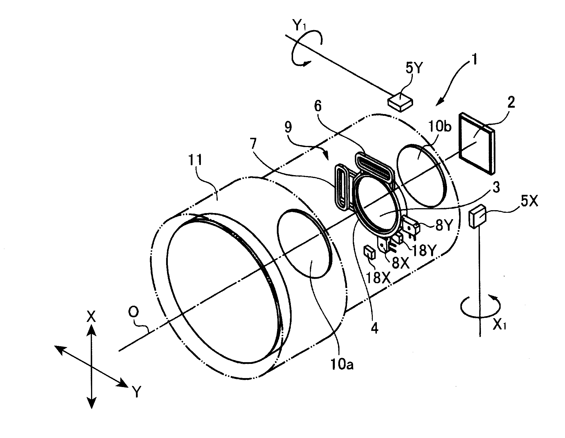
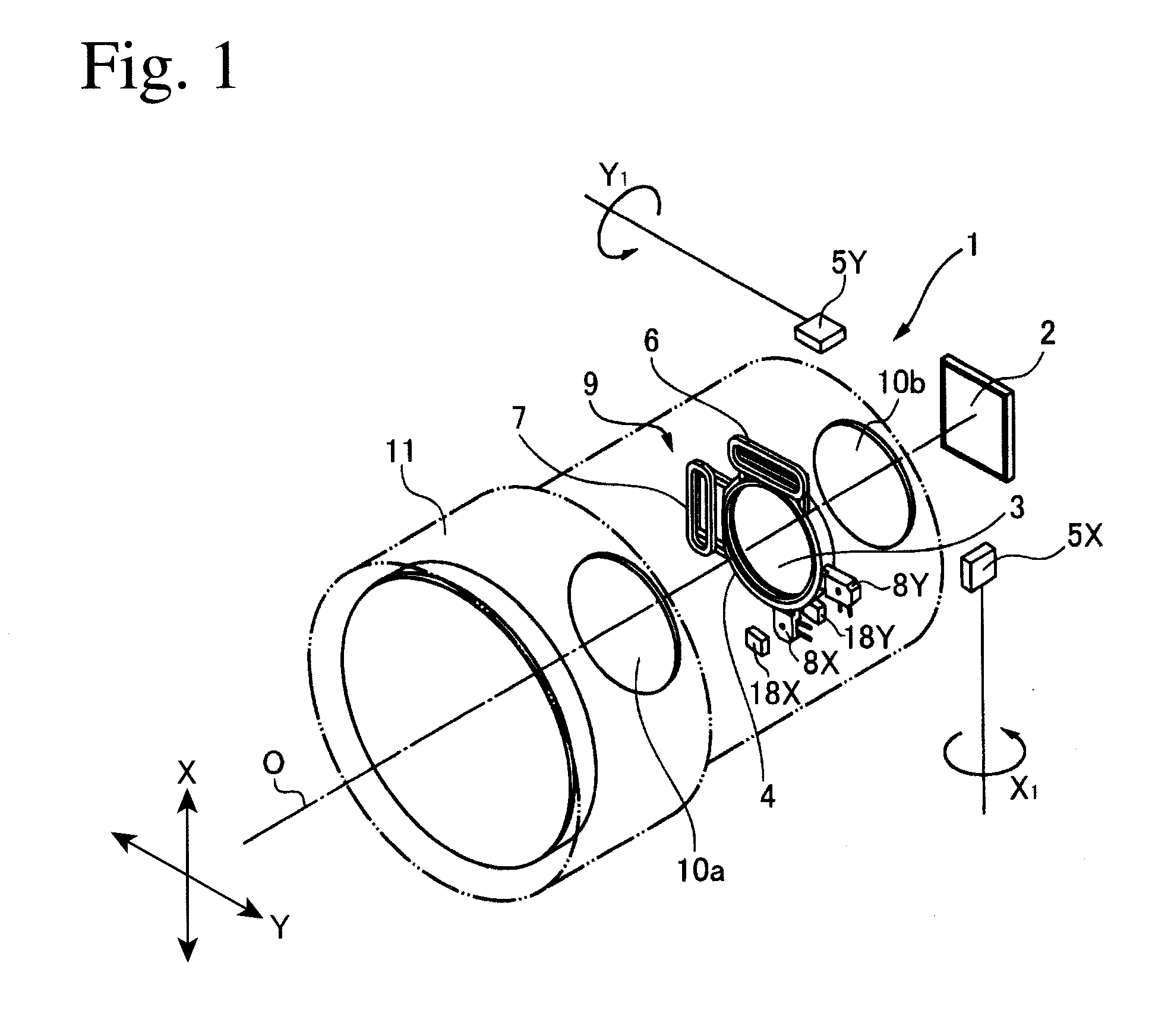
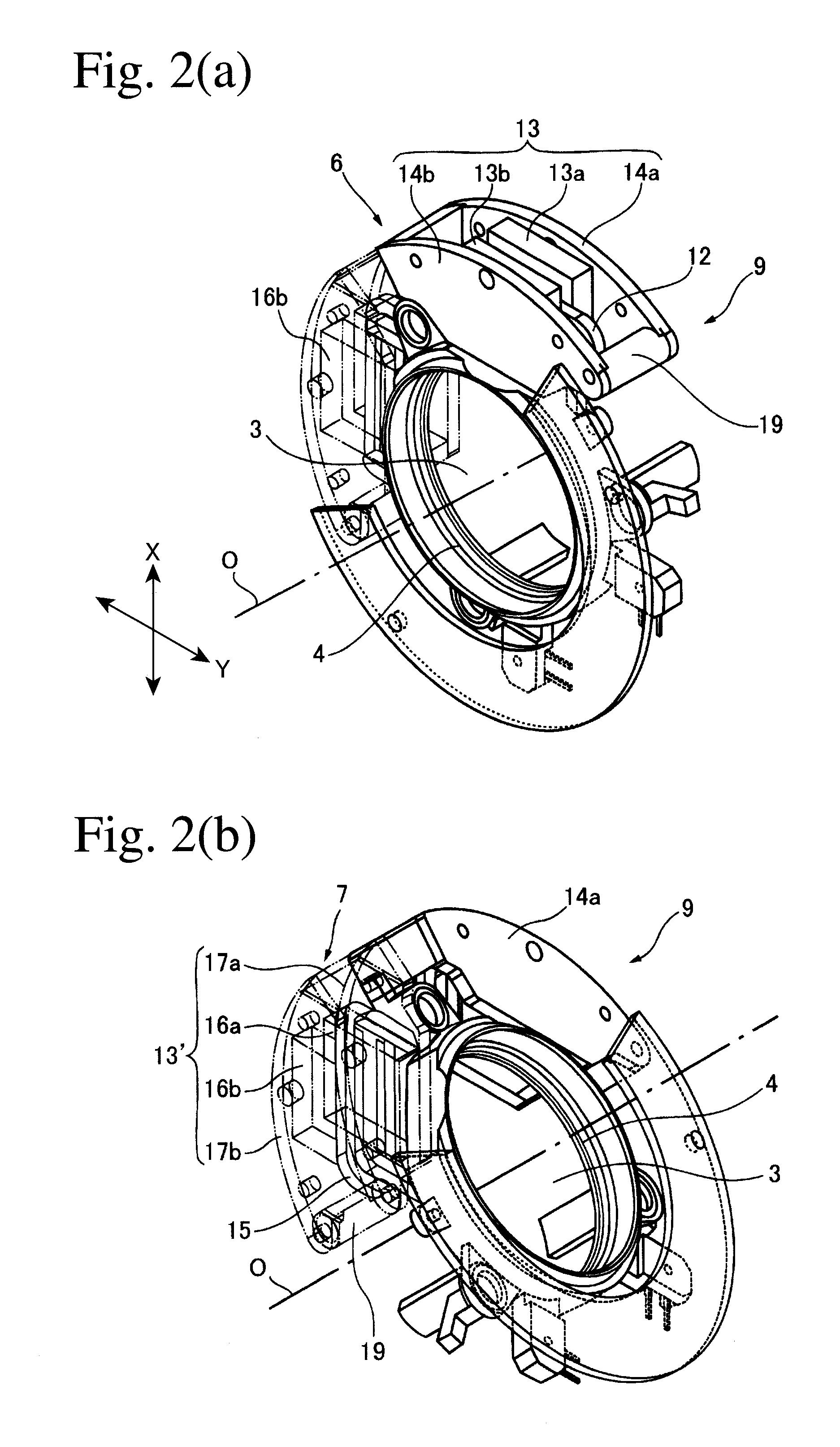
[0010]Accordingly, an object of the present invention is to provide a correction-lens-moving voice coil motor with reduced electric power consumption for moving the correction lens and capable of generating stable thrust even at the longest movement distance of the coil, an anti-vibration device comprising this correction-lens-moving voice coil motor, and an interchangeable lens unit and an optical apparatus comprising this anti-vibration device.

Problems solved by technology

On the other hand, the correction of hand vibration by the lens-shifting system is excellent in the function of correcting hand vibration but disadvantageous in miniaturization, so that it is mainly used in interchangeable lens units for digital, single-lens reflex cameras and digital video cameras.
Because this VCM has the unmagnetized neutral zones 13f1, 13f2 between the opposing permanent magnets 13c, 13d, a volume percentage of the permanent magnet contributing to the generation of magnetic flux in the magnetic gap is smaller, resulting in a smaller amount of magnetic flux, meaning poorer magnetic efficiency.
Like the unmagnetized neutral zones in Japanese Patent 4,181,663, the magnetic gap between a pair of permanent magnets is undesirable for magnetic efficiency, because it has a magnetic flux density reduced correspondingly to the volume decrease of the permanent magnets as compared with the gap-free structure.
In addition, Japanese Patent 2,641,172 does not describe the relations among the effective conductor width of the coil, the magnetic pole width of each permanent magnet and the longest one-direction movement distance of the coil, failing to take into consideration decrease in electric power consumption at the time of correcting hand movement.

Method used


Image

  • Correction-lens-moving voice coil motor, Anti-vibration device, interchangeable lens unit and optical apparatus
  • Correction-lens-moving voice coil motor, Anti-vibration device, interchangeable lens unit and optical apparatus
  • Correction-lens-moving voice coil motor, Anti-vibration device, interchangeable lens unit and optical apparatus

Examples


example 1

[0089]In the correction-lens-moving voice coil motor of the present invention 6 having the structure shown in FIG. 4(a), the thrust of the first coil 12, when the first coil 12 moved from the center position P0 in the F1 direction (X direction) by the longest one-side movement distance Sc (1.5 mm), was determined under the conditions shown in Table 1, using a commercially available, three-dimensional magnetic field analysis simulation software. Direct current supplied to the first coil 12 was 0.1 A, with voltage of 2.0 V. The magnetic flux density in the magnetic gap G was 0.94 T, and the thrust constant was 2.4-2.7 N / A. The results are shown in FIG. 8. The thrust is expressed by a relative value when the thrust at the original position was 100%. Because the conditions of Example 1 were Wm=5.0 mm, and (Wb+St)=4.5 mm, K was 1.1, meeting the basic condition of the present invention.

example 2

[0093]The electric power consumption of the first coil and the size of the voice coil motor were evaluated by the same magnetic field analysis simulation as in Example 1 except for changing the coil width, the longest movement distance and the magnetic pole width. The results are shown in Table 2.

[0094](1) Electric Power Consumption of First Coil

[0095]Because the electric power consumption of the first coil increases in proportion to a ratio Ist(=Im / I0), wherein Im is current necessary for generating the maximum thrust when reaching the longest movement distance (the longest stroke), and I0 is current flowing when the first coil is at the center position, the electric power consumption of the first coil was evaluated by the ratio Ist. The evaluation standard is as follows:[0096]Good Ist is 1.0 or more and less than 1.20,[0097]Fair Ist is 1.20 or more and less than 1.25, and[0098]Poor Ist is 1.25 or more.

[0099](2) Size of Voice Coil Motor

[0100]The size of the voice coil motor was eva...


PUM


Abstract

A voice coil motor for moving a correction lens comprising a magnet unit comprising a pair of yokes and at least one permanent magnet for defining a magnetic gap, and a coil disposed in the magnetic gap, to cause the relative linear movement of the magnet unit and the coil by current supplied to the coil; the permanent magnet having different magnetic poles adjacent to each other along the movement direction on a surface opposing the magnetic gap; the width of the permanent magnet in the movement direction being two times the width Wm of the magnetic poles; the width Wa of the coil in the movement direction being smaller than the width 2Wm of the permanent magnet; and the effective conductor width Wb of the coil, the magnetic pole width Wm of the permanent magnet and the longest movement distance St of the correction lens meeting the conditions of Wm=(Wb+St)×K, wherein K is a constant meeting 1<K≦1.5.

Description

FIELD OF THE INVENTION[0001]The present invention relates to a voice coil motor for moving a lens for correcting the blurring of image due to hand movement, etc. in optical apparatuses such as cameras, binoculars, etc., an anti-vibration device driven by the voice coil motor, and an interchangeable lens unit and an optical apparatus comprising the anti-vibration device.BACKGROUND OF THE INVENTION[0002]In optical apparatuses such as digital still cameras, as the number of pixels and the magnification of zooming increase, the blurring of image due to hand vibration (including tremble of hands in addition to the sway of arms or a body) while photographing increases. To prevent it, the optical apparatuses have become comprising anti-vibration devices. The anti-vibration device is an apparatus for moving image to the right position on an image sensor such as CCD, etc. depending on hand movement detected while photographing.[0003]The anti-vibration device mainly uses an image-sensor-shift...

Claims


Application Information

Patent Timeline
Patent Type & Authority Applications(United States)
IPC IPC(8): G02B27/64G02B7/02
CPCG03B5/00G03B5/02G02B27/646G02B7/02G02B27/64H04N5/23287H04N23/687
Inventor MOTOIKE, TAKASHIOOARA, HIROYUKIKURIYAMA, YOSHIHIKO
Owner KENKOTOKINA CORP
Why Eureka
Try Eureka