Electrical connection structure for piezoelectric element and head suspension

a piezoelectric element and connection structure technology, applied in the direction of maintaining the head carrier alignment, manufacturing tools, instruments, etc., can solve the problem of dubious electrical connection between the two parts

Active Publication Date: 2011-11-17
NHK SPRING CO LTD
View PDF12 Cites 63 Cited by
  • Summary
  • Abstract
  • Description
  • Claims
  • Application Information

AI Technical Summary

Benefits of technology

[0025]The recesses on the conductive terminal surface layer are formed by laser processing, and therefore, no contamination occurs around the terminal.
[0026]According to the second aspect, the improved electrical connection and maintained electrical characteristics between the electrode surface of the piezoelectric element and the terminal surface of the wiring member surely apply a voltage to the piezoelectric element and reliably move the magnetic head relative to the base for a very short distance in a sway direction.

Problems solved by technology

This means that the original bonding strength of the conductive adhesive is not fully used to bond the terminal surface and electrode surface together, and therefore, the reliability of electrical connection between them is dubious.

Method used


Image

  • Electrical connection structure for piezoelectric element and head suspension
  • Electrical connection structure for piezoelectric element and head suspension
  • Electrical connection structure for piezoelectric element and head suspension

Examples


Embodiment Construction

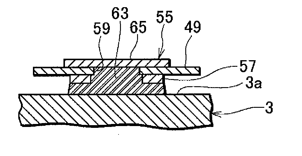
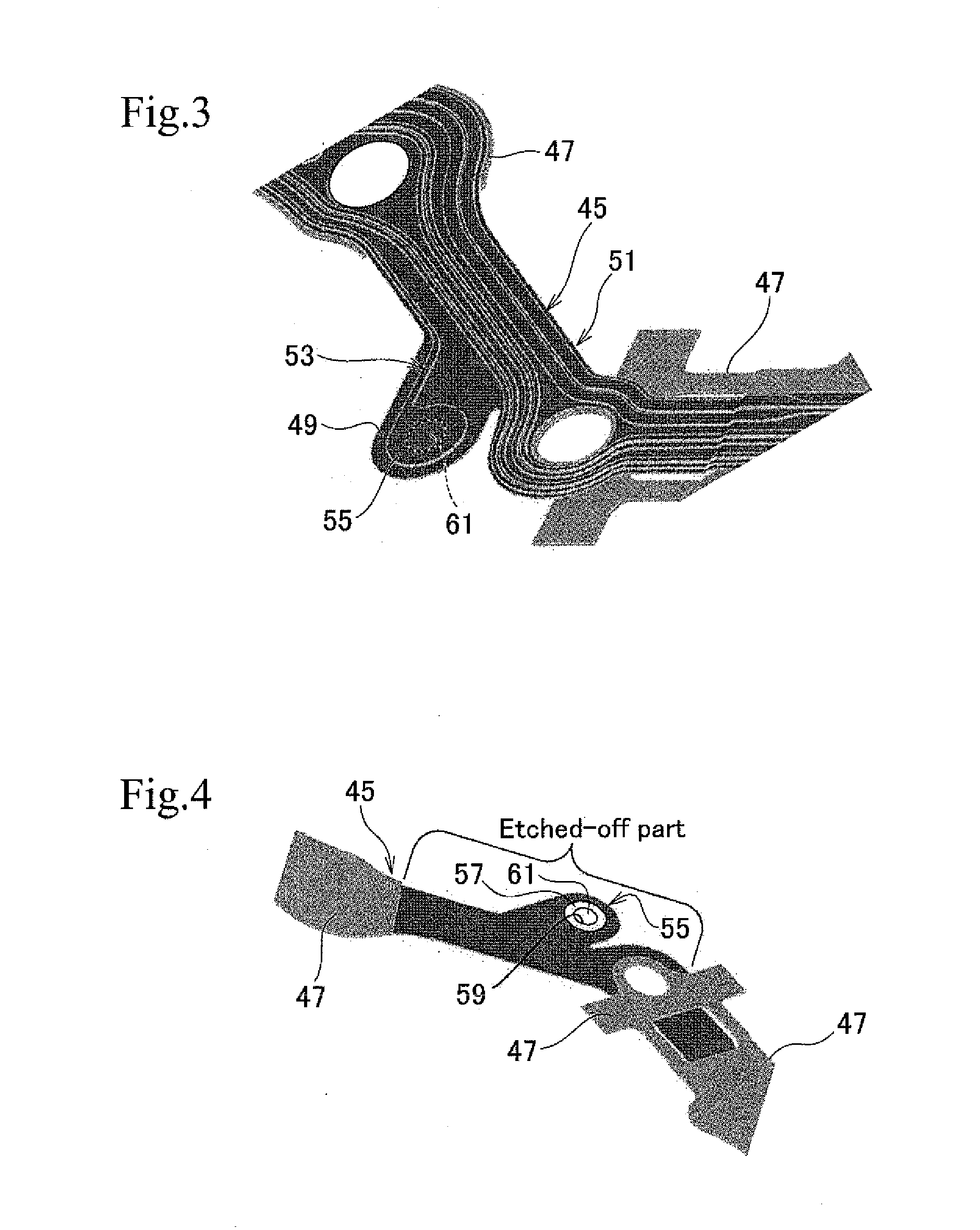
[0054]An embodiment of the present invention will be explained with reference to the drawings. The embodiment forms one or more recesses by laser processing on a conductive terminal surface layer formed on a terminal surface of a head suspension, to improve the reliability of electrical connection between the terminal surface and an electrode surface of a piezoelectric element of the head suspension, maintain the electrical characteristics of the terminal, and prevent contamination of the terminal.

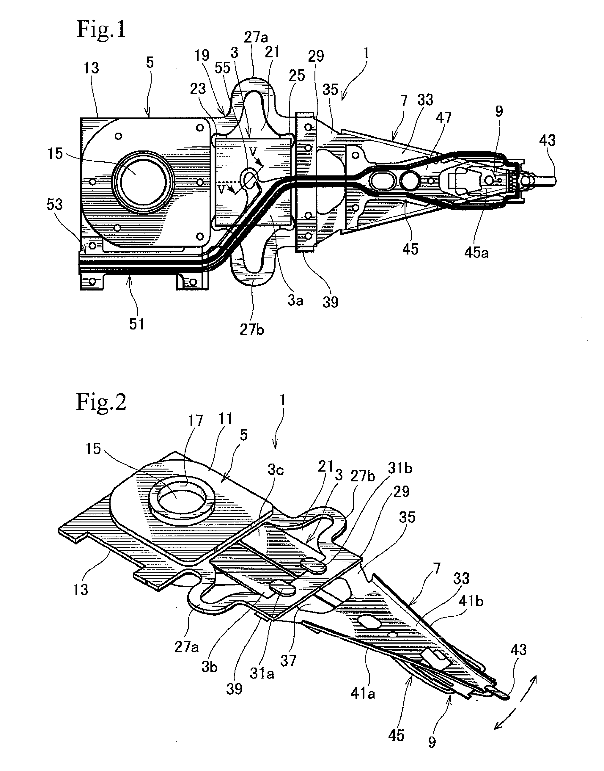
[0055]FIG. 1 is a plan view illustrating a head suspension 1 according to an embodiment of the present invention and FIG. 2 is a perspective view illustrating the same.

[0056]As illustrated in FIGS. 1 and 2, the head suspension 1 includes a piezoelectric element 3 for which an electrical connection structure according to an embodiment of the present invention is applied, a base 5, a load beam 7 attached to the base 5, and a read-write head 9 attached to a front end of the load beam 7.

[0057]...


PUM

PropertyMeasurementUnit
thicknessaaaaaaaaaa
thicknessaaaaaaaaaa
thicknessaaaaaaaaaa

Abstract

An electrical connection structure connects a piezoelectric element to a flexure with a conductive adhesive. An electrode surface is formed on the piezoelectric element, and a terminal surface is formed on the wiring member and is smoother than the electrode surface. A the gold plate layer is formed on the terminal surface and is connected to the electrode surface with the conductive adhesive. At least one recess is formed by laser processing on the conductive terminal surface layer. The electrical connection structure substantially equalizes the surface roughness of the terminal surface with the gold plate layer to that of the electrode surface, improves a bonding strength on the terminal surface nearly to that on the electrode surface, enhances the reliability of electrical connection between the electrode surface and the terminal surface, maintains electrical characteristics of the terminal surface, and prevents contamination around the terminal surface.

Description

BACKGROUND OF THE INVENTION[0001]1. Field of the Invention[0002]The present invention relates to an electrical connection structure between a piezoelectric element and a wiring member, as well as to a head suspension employing the electrical connection structure.[0003]2. Description of Related Art[0004]Small-sized precision information devices are rapidly advancing, and for use with such devices, needs for micro-actuators capable of conducting positioning control for very small distances are increasing. Such micro-actuators are highly needed by, for example, optical systems for correcting focuses and inclination angles, ink jet printers for controlling ink heads, and magnetic disk drives for controlling magnetic heads.[0005]The magnetic disk drives increase storage capacities by increasing the number of tracks per inch (TPI), i.e., by narrowing the width of each track on a magnetic disk.[0006]The magnetic disk drive, therefore, needs an actuator capable of precisely positioning the ...

Claims


Application Information

Patent Timeline
Patent Type & Authority Applications(United States)
IPC IPC(8): G11B21/24H01R4/00B23K26/00G11B5/596G11B5/60G11B21/10H01L41/09H01L41/187
CPCG11B5/4853H01R13/03H01R4/04H01L41/0475H10N30/875
Inventor KIN, TATSUHIRO
Owner NHK SPRING CO LTD
Why Eureka
Try Eureka