Printing apparatus

a printing apparatus and printing head technology, applied in printing, typewriters, other printing apparatuses, etc., can solve the problems of increasing the likelihood of the leading end of the sheet floating and touching the nozzle, increasing the distance between the conveying roller and the print head, and achieving the effect of high printing throughpu

Active Publication Date: 2011-11-17
CANON KK
View PDF3 Cites 25 Cited by
  • Summary
  • Abstract
  • Description
  • Claims
  • Application Information

AI Technical Summary

Benefits of technology

[0007]In view of the above-described problems, the present invention provides a printing apparatus capable of duplex printing, which can precisely print images on both surfaces of a sheet and achieve high printing throughput.

Problems solved by technology

Because the speed sensor (laser Doppler sensor) requires a large installation space, the distance between the conveying roller and the print heads is large.
This increases the likelihood of the leading end of the sheet floating and touching nozzles in the print head on the most upstream side, when the sheet is introduced and passes from the conveying roller to the print heads.
However, the smaller the distance between the speed sensor and the print heads, the more the following problems become apparent.
1. It is more likely to fail in completing calculation by the speed sensor and control of ink ejection timing from when the sheet passes through a measurement position, where the speed sensor performs measurement, to when it reaches the print head on the most upstream side.
Because this problem becomes significant as the sheet conveyance speed increases, it is difficult to increase the printing speed.
2. As the distance between a printing area, in which the print heads perform printing, and the measurement position of the speed sensor is reduced, the likelihood of cockling (local sheet floating), which occurs when the sheet absorbs ink immediately after printing, affecting the measurement position increases.
Such floating of the sheet occurring at the sensor's measurement position can cause a measure error.

Method used


Image

  • Printing apparatus
  • Printing apparatus
  • Printing apparatus

Examples


Embodiment Construction

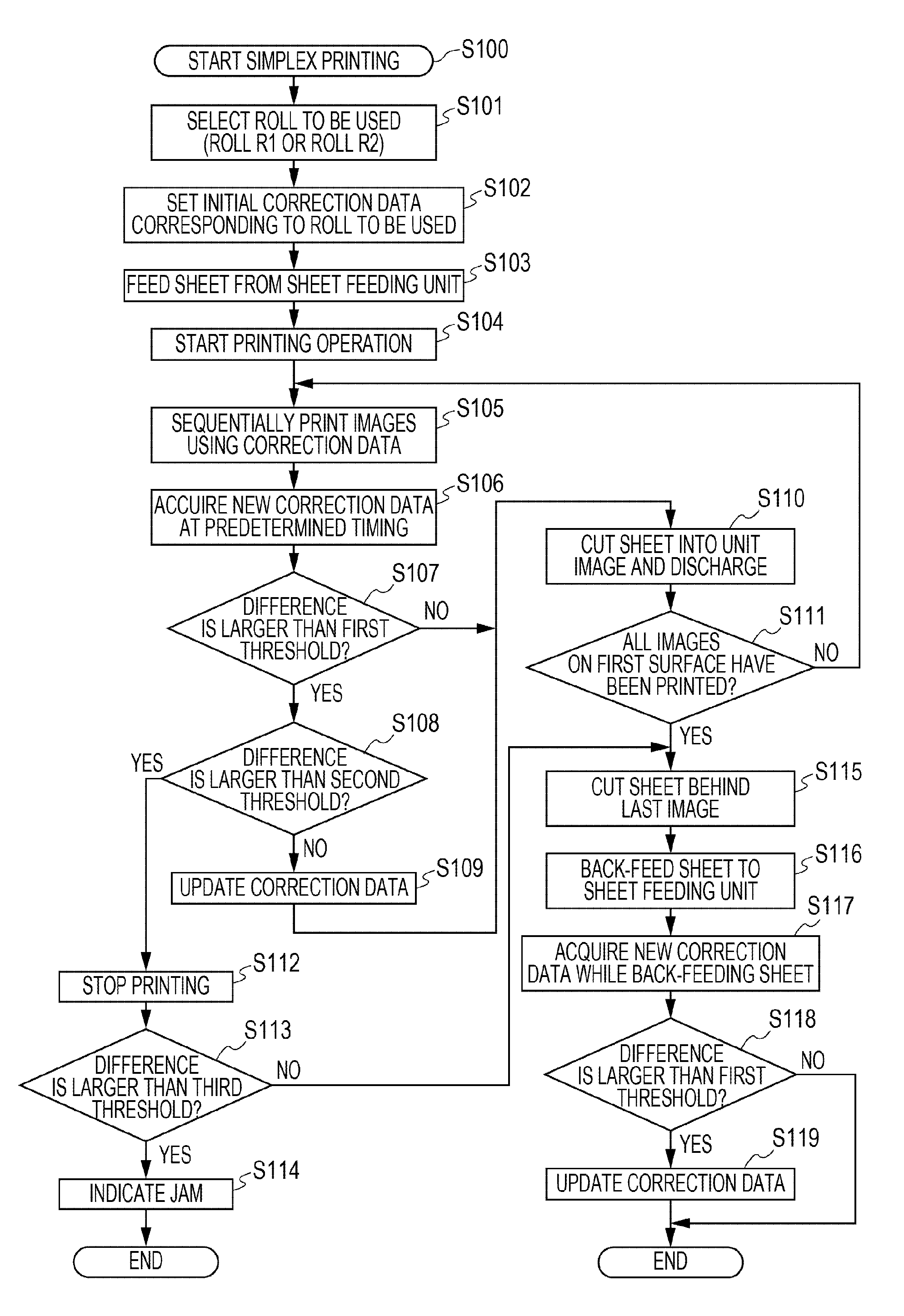
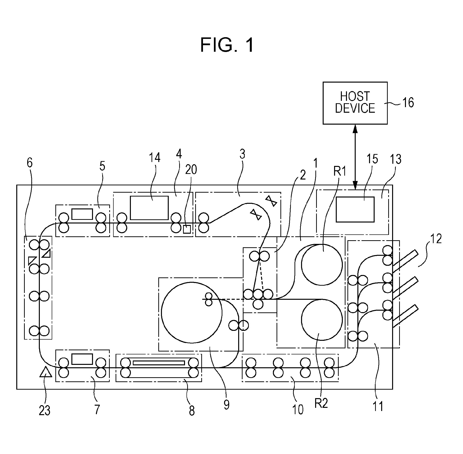
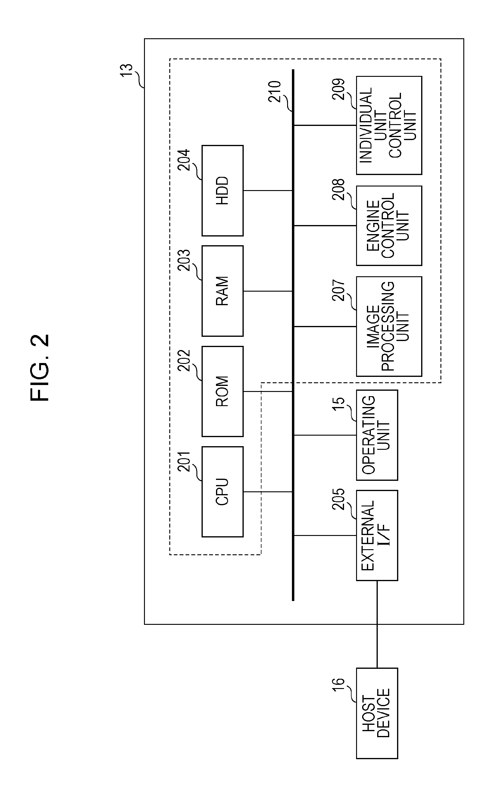
[0024]An embodiment of a printing apparatus employing an ink jet method will be described. A printing apparatus of this example is a high-speed line printer that uses a long continuous sheet (a continuous sheet that is longer than a repeating printing unit, i.e., “one page” or “a unit image”, in the conveying direction and that can be used in both simplex printing and duplex printing. Such a printing apparatus is suitable for use in, for example, printing labs, in which mass printing is required. Note that, herein, a plurality of small images, letters, and blank spaces existing in the area of one printing unit (one page) are collectively referred to as one unit image. That is, a unit image means one printing unit (one page) in the case where a plurality of pages are sequentially printed on a continuous sheet. The length of a unit image depends on the size of the image to be printed. For example, an L-sized picture has a length of 135 mm in the sheet conveying direction, and an A4-si...


PUM


Abstract

A control unit includes a memory storing correction data obtained by associating information acquired by a first acquisition unit (rotary encoder) with information acquired by a second acquisition unit (direct sensor) with respect to, at least one rotation of a conveying roller. When a plurality of images are sequentially printed on a first surface and a second surface of a continuous sheet, the control unit reads the correction data corresponding to the rotation information acquired by the first acquisition unit from the memory and corrects at least one of driving control of a print head and driving control of the roller. The correction data used in printing on the first surface of the sheet is different from that used in printing on the second surface of the sheet.

Description

BACKGROUND OF THE INVENTION[0001]1. Field of the Invention[0002]The present invention relates to printing apparatuses that convey sheets and perform printing.[0003]2. Description of the Related Art Japanese Patent Laid-Open No. 2009-6655 discloses a printing apparatus that directly measures the speed of a sheet surface using a speed sensor to control the timing at which ink is ejected from print heads. FIG. 8 is a simplified diagram showing a printing apparatus disclosed in FIG. 25 of Japanese Patent Laid-Open No. 2009-6655. A roll of sheet 500 is conveyed by a conveying roller pair 501 on the upstream side and a conveying roller pair 502 on the downstream side and is subjected to printing by print heads 503. A speed sensor 504 (a laser Doppler sensor) that directly measures the moving speed of the sheet is disposed between the conveying roller pair 501 on the upstream side and the print heads 503. The timing of driving the print heads 503 is corrected based on the sheet conveyance ...

Claims


Application Information

Patent Timeline
Patent Type & Authority Applications(United States)
IPC IPC(8): B41J11/42
CPCB41J3/60B41J11/42B41J11/008
Inventor IKEDA, YASUHIKOYOSHIDA, MASAHITOKAWAGUCHI, KOICHIROSHIGENO, KENJITAKEUCHI, TOSHIKIIZUMI, MASATOSATO, RYOSUKENIEDA, KENGO
Owner CANON KK
Why Eureka
Try Eureka