
De-icing and/or Anti-icing of a wind turbine component by vibrating a piezoelectric material

a piezoelectric material and wind turbine technology, applied in the field of wind turbines, can solve the problems of excessive mechanical loads, increased vibration problems, and reduced performance of wind turbines, so as to reduce the probability of ice falling from a large height and increase safety

Inactive Publication Date: 2011-11-17
SIEMENS AG
View PDF11 Cites 20 Cited by
  • Summary
  • Abstract
  • Description
  • Claims
  • Application Information

AI Technical Summary

Benefits of technology

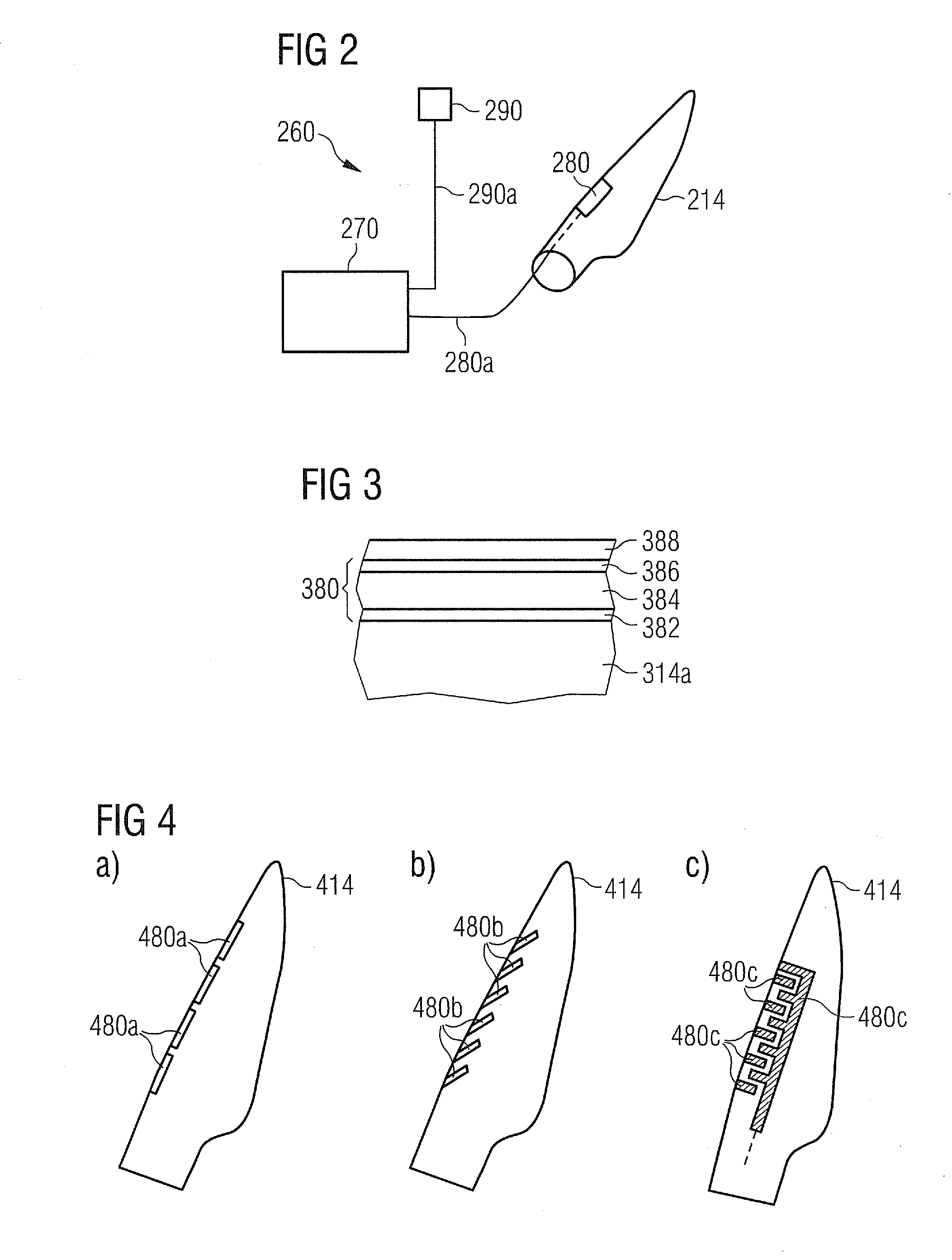
"The patent describes a system for de-icing and preventing ice formation on wind turbine components. The system includes a vibrator that is mounted on the component and an electric generator that supplies an electric signal to the vibrator. The vibrator is made of a piezoelectric material that causes vibrations when an electric field is applied. The vibrations cause the surface of the component to vibrate, which breaks the bond between ice and the surface, allowing the ice to detach from the component. The system can be controlled remotely, making it easy to operate and cost-effective. The vibrator can be embedded within a protective layer to increase its durability. The technical effect of the system is to provide a fast and effective solution for de-icing and preventing ice formation on wind turbine components."

Problems solved by technology

Icing on any exposed part of a wind turbine can occur and cause decreased performance of the wind turbine.
Furthermore e.g. when ice is accumulated on one or more of the rotor blades of a wind turbine, excess vibration problems from uneven blade icing may occur.
This in turn may generate excessive mechanical loads on the wind turbine components leading eventually to wind turbine shut-down or to wind turbine faults.

Method used


Image

  • De-icing and/or Anti-icing of a wind turbine component by vibrating a piezoelectric material
  • De-icing and/or Anti-icing of a wind turbine component by vibrating a piezoelectric material
  • De-icing and/or Anti-icing of a wind turbine component by vibrating a piezoelectric material

Examples


Embodiment Construction

[0056]The illustration in the drawing is schematically. It is noted that in different figures, similar or identical elements are provided with the same reference signs or with reference signs, which are different from the corresponding reference signs only within the first digit.

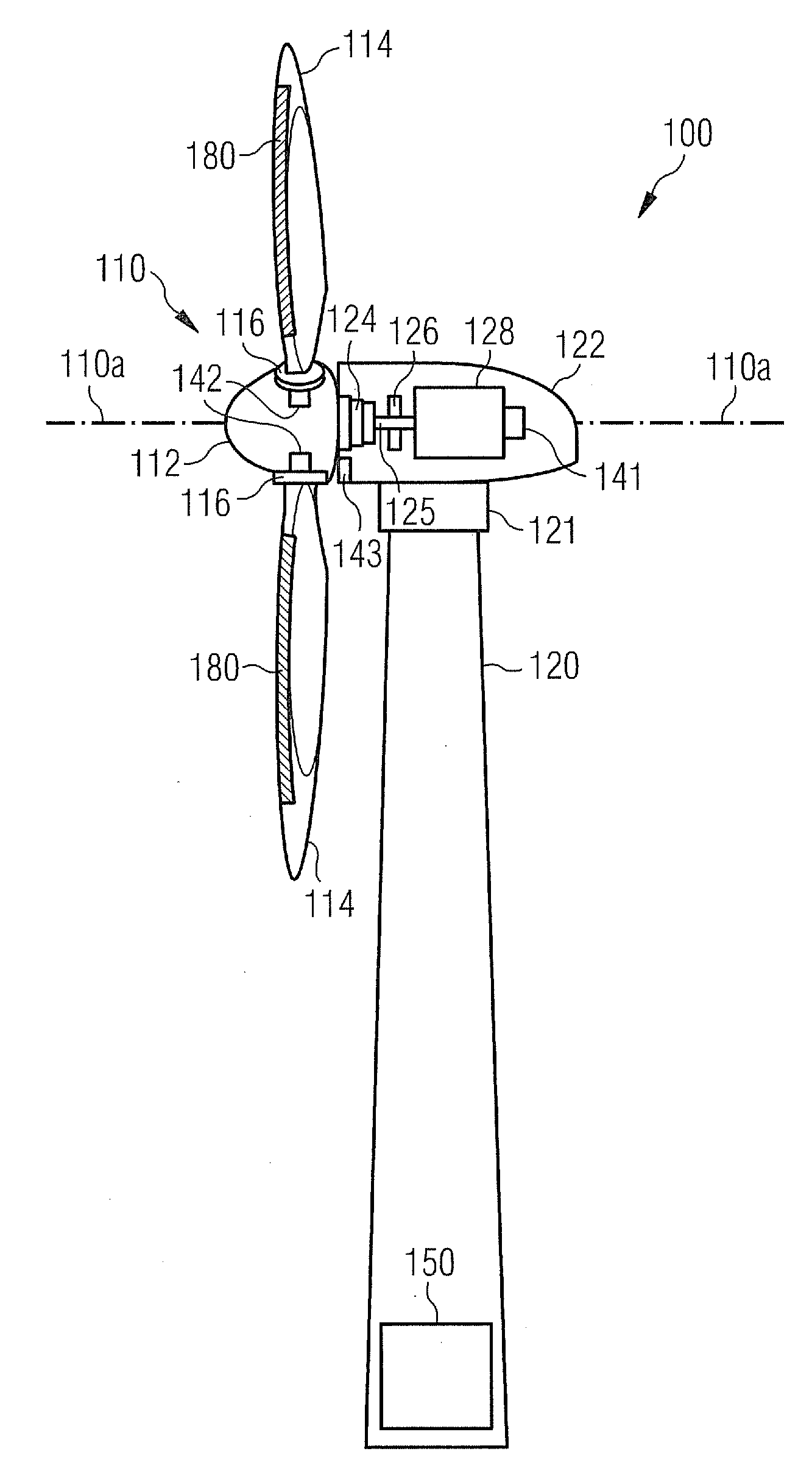
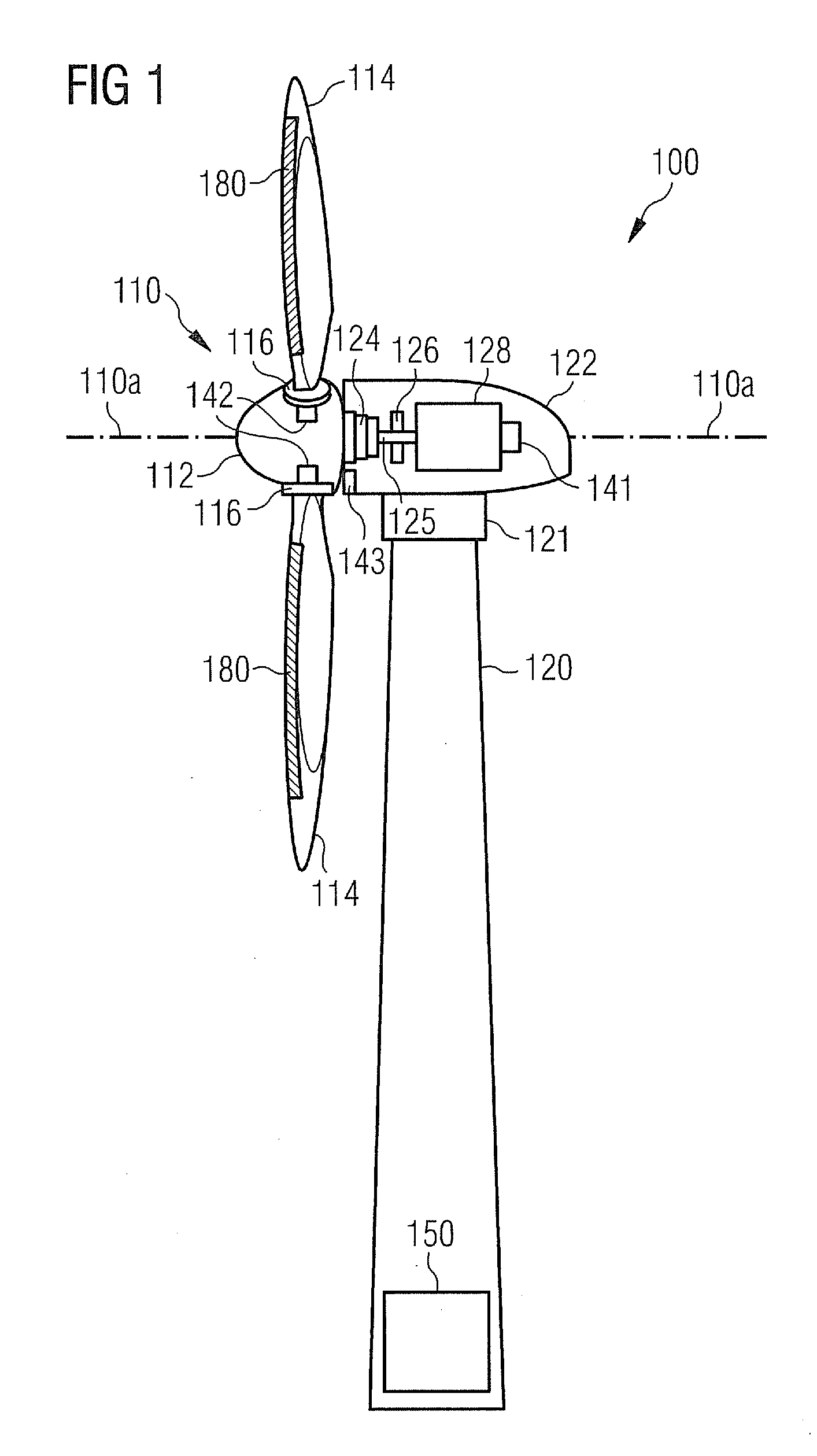
[0057]FIG. 1 shows a wind turbine 100 according to an embodiment of the invention. The wind turbine 100 comprises a tower 120, which is mounted on a non-depicted fundament. On top of the tower 120 there is arranged a nacelle 122. In between the tower 120 and the nacelle 122 there is provided a yaw angle adjustment device 121, which is capable of rotating the nacelle 122 around a non depicted vertical axis, which is aligned with the longitudinal extension of the tower 120. By controlling the yaw angle adjustment device 121 in an appropriate manner it can be made sure, that during a normal operation of the wind turbine 100 the nacelle 122 is always properly aligned with the current wind direction.

[0058]The win...


PUM


Abstract

A system for de-icing and / or for avoiding an icing of a component of a wind turbine is provided. The system includes a vibrator. The vibrator includes a piezoelectric material and which is adapted to be mounted to at least to a portion of the component, and an electric generator, which is adapted to supply an electric signal to the vibrator, wherein the electric signal causes the vibrator to vibrate and to transfer vibrational energy to at least a surface portion of the component. A corresponding method for de-icing and / or for avoiding an icing of a component of a wind turbine is also provided.

Description

CROSS REFERENCE TO RELATED APPLICATIONS[0001]This application claims priority of European Patent Office application No. 10162642.2 EP filed May 12, 2010, which is incorporated by reference herein in its entirety.FIELD OF INVENTION[0002]The present invention relates to the technical field of wind turbines. In particular, the present invention relates to a system and to a method for de-icing and / or for preventing an icing of a component of a wind turbine.ART BACKGROUND[0003]Icing on any exposed part of a wind turbine can occur and cause decreased performance of the wind turbine. Furthermore e.g. when ice is accumulated on one or more of the rotor blades of a wind turbine, excess vibration problems from uneven blade icing may occur. This in turn may generate excessive mechanical loads on the wind turbine components leading eventually to wind turbine shut-down or to wind turbine faults.[0004]Problems related to icing can be prevented by at least one of two different measures: A first me...

Claims


Application Information

Patent Timeline
Patent Type & Authority Applications(United States)
IPC IPC(8): F01D5/08
CPCF03D11/0025F05B2220/709Y02E10/722F05B2250/314Y02E10/721F05B2250/12F03D80/40Y02E10/72
Inventor LIBERGREN, PETER
Owner SIEMENS AG
Learn More