Starter Alternator Assembly Comprising a Poli-V Belt and Poli-V Belt

a technology of starter alternator and poli-v belt, which is applied in the direction of v-belts, belts/chains/gearrings, mechanical instruments, etc., can solve the problems of fluctuating torque, affecting the and affecting the service life of the starter alternator

Active Publication Date: 2011-11-17
DAYCO EURO
View PDF15 Cites 11 Cited by
  • Summary
  • Abstract
  • Description
  • Claims
  • Application Information

AI Technical Summary

Benefits of technology

[0013]The aim of the present invention is to provide a drive belt of the poly-V type, particularly for driving

Problems solved by technology

In addition, during the starting step, until the combustion has reached the steady-state condition, there occur irregularities of combustion that induce a fluctuating torque on the belt drive.
The consequent stresses can jeopardize the duration of the belt.
This problem is particularly felt in motor vehicles provided with starter-alternator assemblies which are turned off and started again at each stoppage of the vehicle, and in which consequently the belt is required to withstand a very high number of cycles of starting of the vehicle.
On account of the peaks of tensile force, the deformation of the mix and hence of the belt is very high and, even th

Method used


Image

  • Starter Alternator Assembly Comprising a Poli-V Belt and Poli-V Belt
  • Starter Alternator Assembly Comprising a Poli-V Belt and Poli-V Belt
  • Starter Alternator Assembly Comprising a Poli-V Belt and Poli-V Belt

Examples


examples 1-3

[0070]Elongation tests were conducted on resistant inserts of a belt made according to the invention and according to the known art.

[0071]The specifications of the tests derive from the SAEJ2432 standard, with the introduction of some modifications, given in what follows, in the dimensions of the pulleys and in the environmental conditions so as to render the testing conditions more stringent.

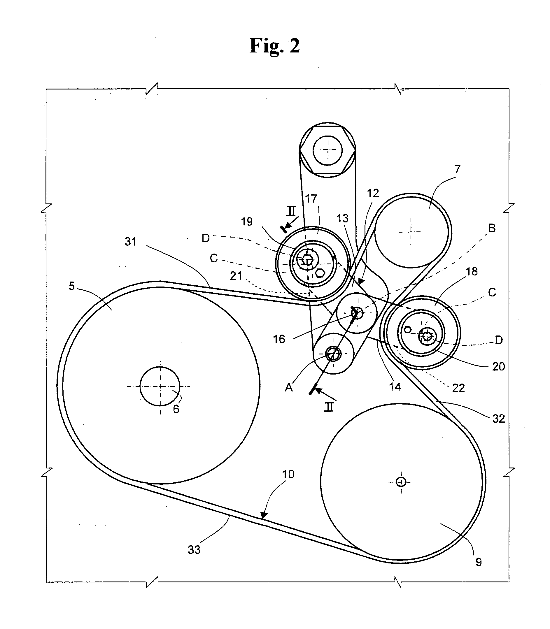
[0072]The belts were tested in the drive assembly envisaged by the standard and illustrated in FIG. 6, whilst the results of the tests are shown in FIG. 7.

[0073]The test was conducted by installing the belt and then setting a tensile force of the belt of 100 N / rib using a dead weight designated by D2 in the figure.

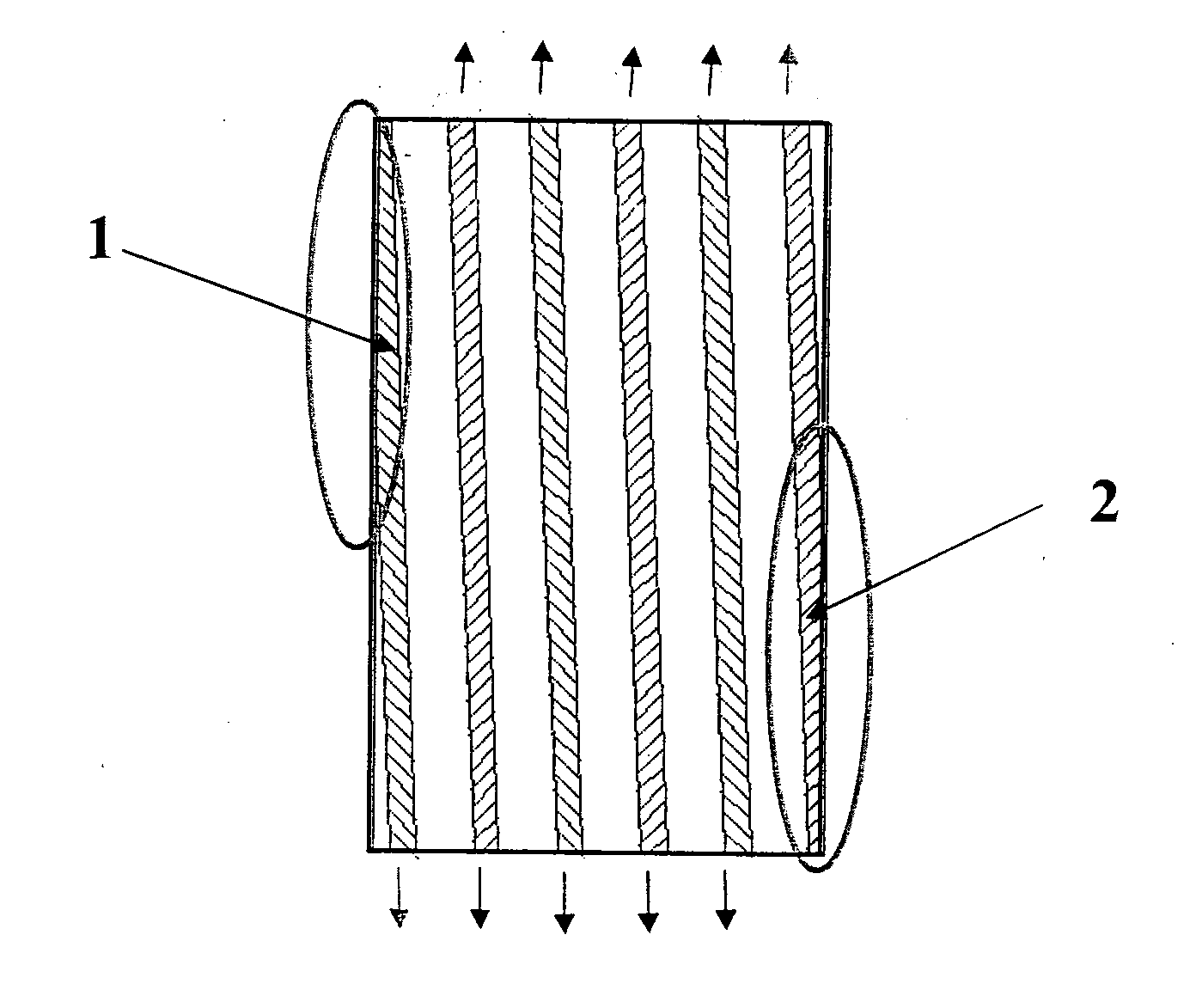
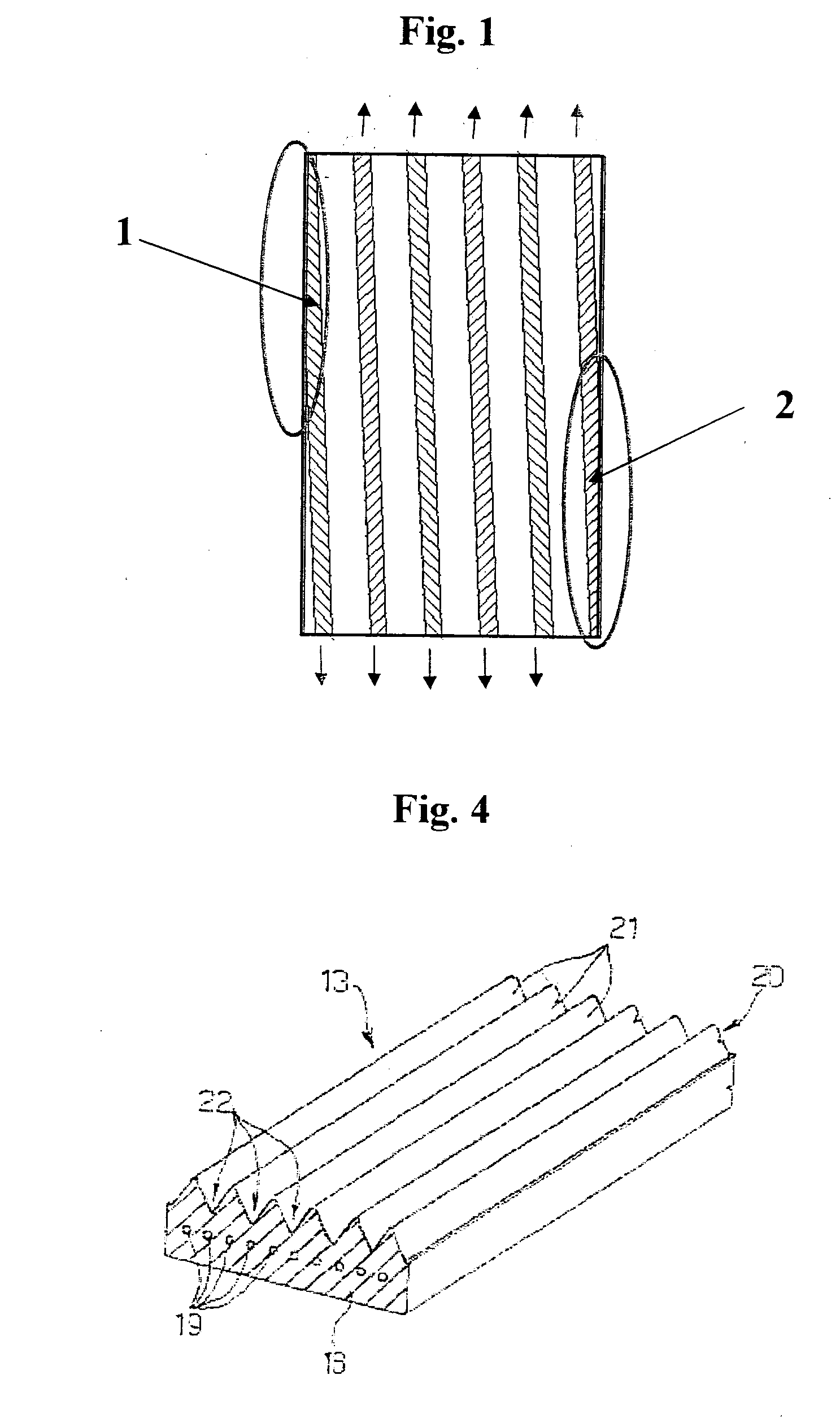
[0074]The belts tested had a body made of EPDM, three ribs, and an effective length of 1050 mm (whilst the standard envisages a length of 1200 mm).

[0075]The pulleys of the drive assembly had the following diameters:

D1 (drive pulley) 120 mm

D2 (idler) 45 mm

D3 (driven pulley) 120 mm

D4 (i...

examples 4-6

[0079]Tests were performed applying a tensile force set using an MTS dynamic pulsator, the instrumentation described in the patent No. EP1669637<), in a drive assembly as schematically illustrated in FIG. 8. Tests for measurement of the dynamic modulus on poly-V belts with said types of instrumentation are also described in the patent No. EP1669637, but said tests are extremely complex. The tests were conducted with a simplified procedure so as to ensure a better reproducibility.

[0080]The results of the tests conducted appear in FIG. 9, which compares poly-V belts comprising resistant inserts made according to the known art, and precisely of aramide, with poly-V belts comprising resistant inserts made of two different materials (hybrid inserts) and precisely with a carbon-thread structure wound by glass filaments as illustrated in FIG. 5 and resistant inserts made of carbon alone.

[0081]The materials and the characteristics of the cords appearing in the graph are given in the table b...


PUM

PropertyMeasurementUnit
Forceaaaaaaaaaa
Forceaaaaaaaaaa
Forceaaaaaaaaaa

Abstract

Starter-alternator assembly including a poly-V belt comprising a body made of elastomeric material, a plurality of filiform resistant inserts longitudinally embedded in the body, and a coupling portion integrally connected to the body and comprising a plurality of V-shaped ribs set alongside one another and alternating with V-shaped grooves. The belt has a dynamic modulus, with a tensile force pre-set at 600 N at a frequency 15 Hz, that after 10 000 cycles is higher than 110 000 N/rib/branch, and is advantageously made with resistant inserts obtained from at least one first fibre material and one second fibre material.

Description

TECHNICAL FIELD[0001]The present invention relates to a drive belt, particularly for driving accessory members of an internal-combustion engine, of the multiple-groove or poly-V type. In particular, the poly-V belt according to the present invention is applied in a belt drive that connects an engine shaft of the internal-combustion engine with a reversible electric machine, or motor-alternator, commonly known as “starter-alternator”, having the dual function of starting motor and of current generator.BACKGROUND ART[0002]A belt drive for accessories generally comprises a drive pulley connected to a crankshaft of the internal-combustion engine of a motor vehicle, at least one second pulley and one third pulley connected respectively to an alternator and to an accessory, for example a hydraulic pump, and a belt for connecting the pulleys together.[0003]In order to start the engine in a fast and silent way, in the engineer it is necessary for the torque supplied by the electric machine ...

Claims


Application Information

Patent Timeline
IPC IPC(8): F16G5/08F16H7/12F16H7/02
CPCF16G5/08F16H7/1281F16H2007/0874
Inventor TRAPPOLINI, CARLODI MECO, MARCO
Owner DAYCO EURO
Why Eureka
Try Eureka