
Regenerative Hydraulic Circuit For Dump Truck Bin Lift Cylinder

Active Publication Date: 2011-11-24
DEERE & CO
View PDF3 Cites 11 Cited by
  • Summary
  • Abstract
  • Description
  • Claims
  • Application Information

AI Technical Summary

Benefits of technology

[0007]According to the present invention, there is provided an improved control for dump truck bin dumping cylinders, and more specifically, there is provided an improved control system for such cylinders.
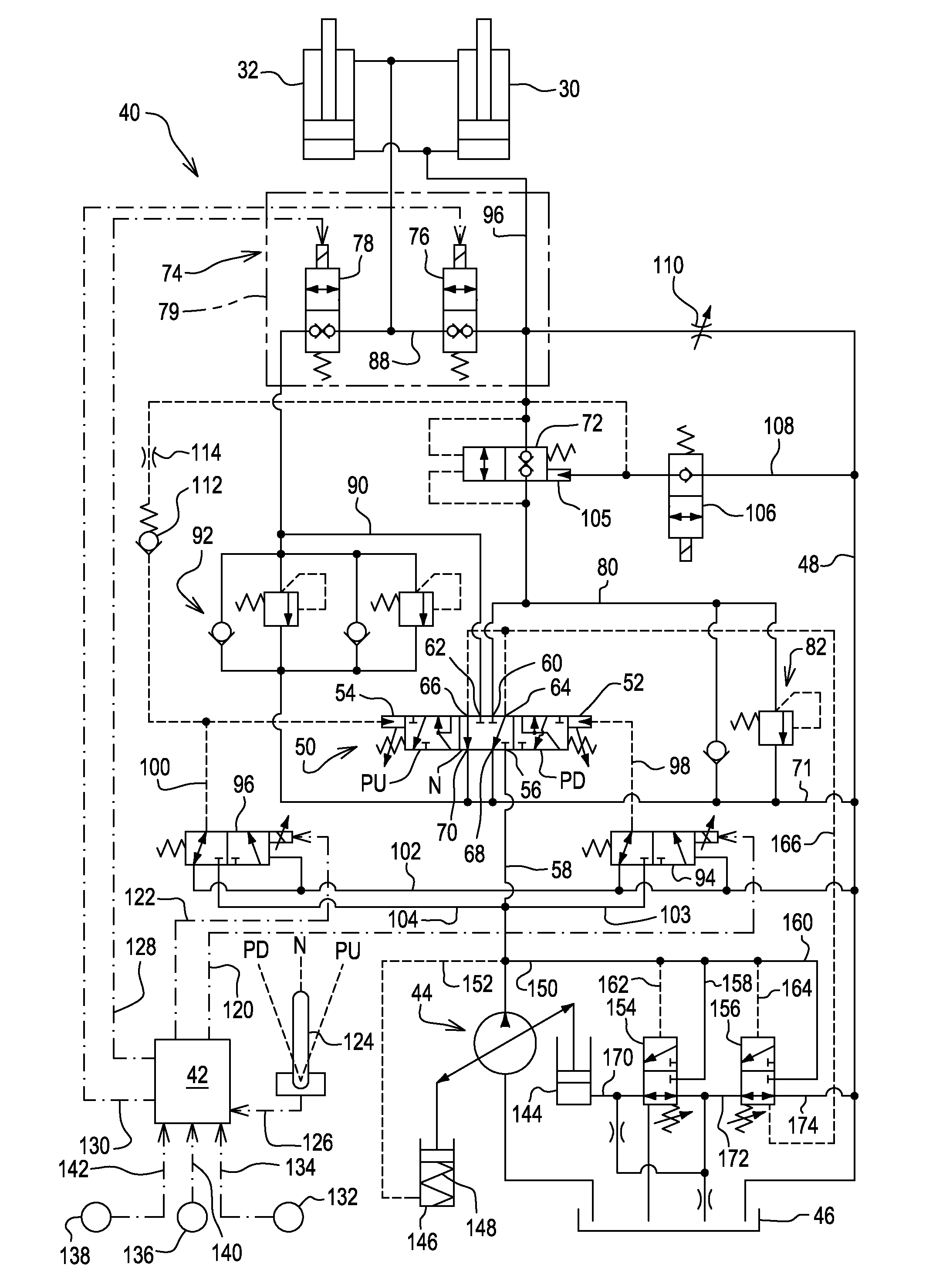
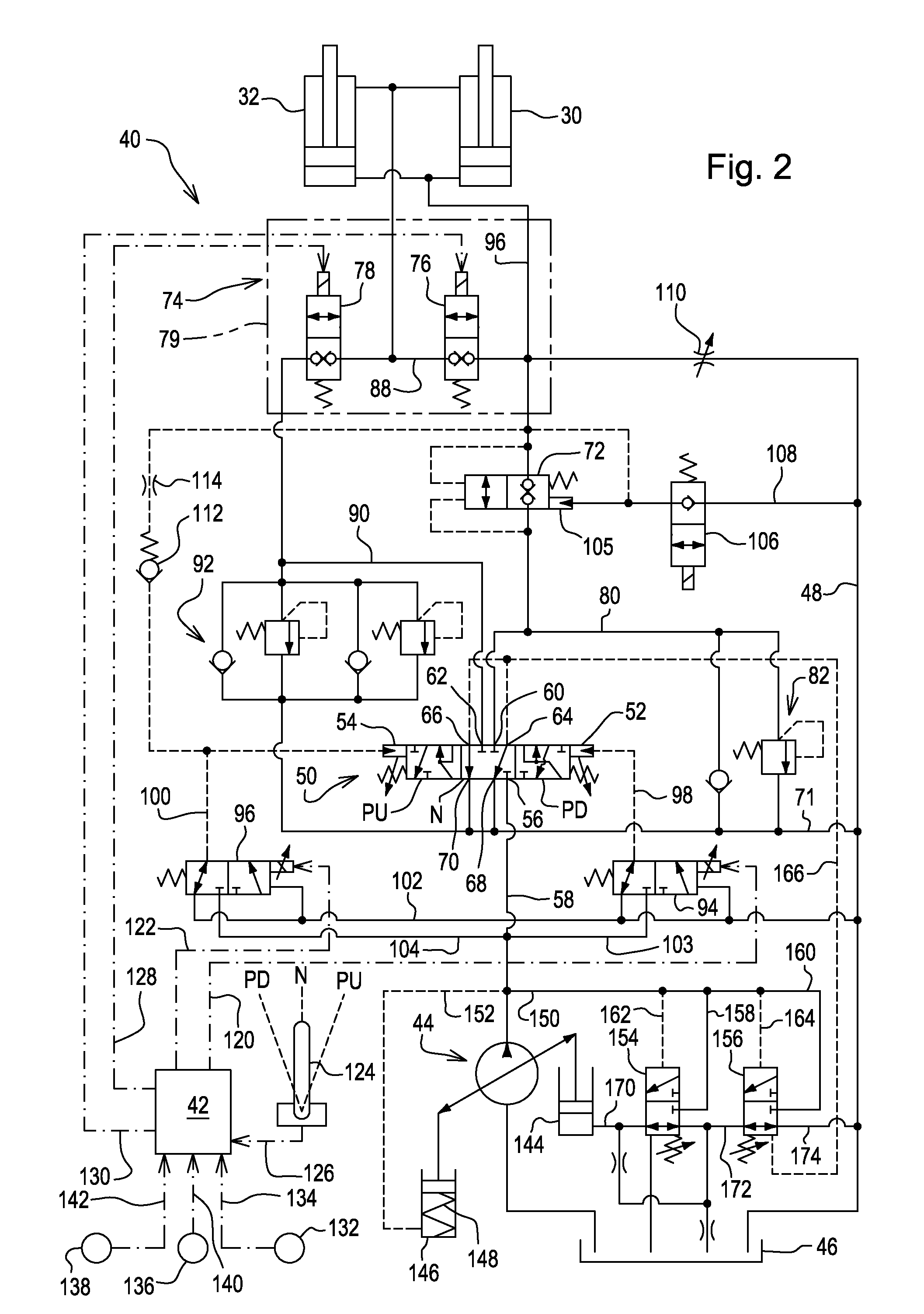
[0009]Specifically, the foregoing object is achieved by providing an electro-hydraulic control system embodying a control valve arrangement operable for supplying fluid to the bin lift cylinder(s) at a high pressure and low flow during a first part of a dump truck bin dumping operation, and thereafter being operable, in response to a predetermined bin weight or bin tip angle, to provide a regenerative flow between rod and head ends of the bin lift cylinders so as to increase the speed of extension of the cylinders.

Problems solved by technology

The problem with multi-stage cylinders is that they are more expensive and prone to leaks and other problems versus a single stage cylinder.

Method used


Image

  • Regenerative Hydraulic Circuit For Dump Truck Bin Lift Cylinder
  • Regenerative Hydraulic Circuit For Dump Truck Bin Lift Cylinder
  • Regenerative Hydraulic Circuit For Dump Truck Bin Lift Cylinder

Examples


Embodiment Construction

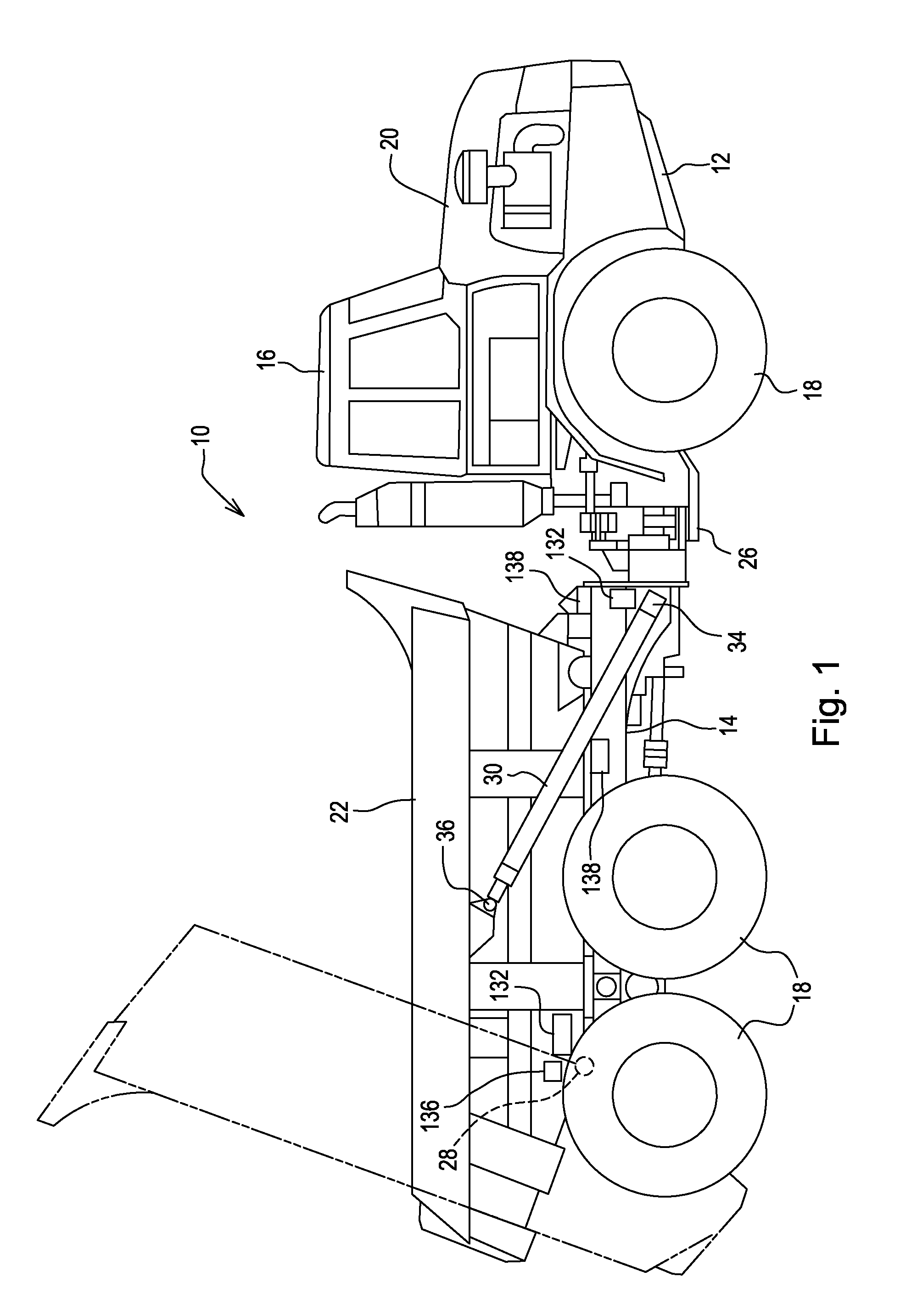
[0015]Referring now to FIG. 1, there is shown an articulated dump truck 10 comprising an articulated frame including front and rear frame sections 12 and 14, respectively, an operator cab 16, a plurality of drive wheels 18 to propel the dump truck 10 over the ground, an engine (not shown) located within an engine compartment 20 to power operation of the dump truck 10, and a bin 22 for holding material to be hauled. The cab 16 is mounted on the front frame section 12. The front and rear frame sections 12 and 14 are pivotally coupled to each other through an articulation joint 26.

[0016]The bin 20 is mounted to a rear region of the rear frame section 14 for pivoting vertically about a horizontal transverse axis defined by right and left coupling pin assemblies 28. Right and left bin lift cylinders 30 and 32 (see FIG. 2) are respectively provided at the opposite sides of the rear frame section 14, with the cylinders 30 and 32 each having a head end pivotally coupled, as at pins 34, to a...


PUM


Abstract

An articulated dump truck is provided with an electro-hydraulic bin control system including a proportional control valve for the bin lift cylinders and including a solenoid-operated regenerative valve assembly mounted adjacent the lift cylinders and being actuated, during lifting the bin for dumping a load of material from the bin, to cause a regenerative flow to occur when the force required by the bin lift cylinders to continue lifting the bin falls to a predetermined force. The force required for tilting the bin is continuously calculated by an electronic control unit taking into account a sensed bin load, a sensed bin tip amount and a sensed side-to-side inclination of the bin. In a simplified second embodiment, the proportional control valve controls the regenerative flow

Description

FIELD OF THE INVENTION[0001]The present invention relates to dump trucks, and more specifically relates to hydraulic circuits for controlling the operation of one or more lift cylinders for the bins of such trucks.BACKGROUND OF THE INVENTION[0002]Articulated dump trucks have a unique configuration that includes bin lift cylinders positioned such that it requires the force exerted by the cylinders to be much greater at the beginning than for the ensuing portion of an operation for dumping a loaded bin. Stated otherwise, the hydraulic pressure required by the cylinders to dump the load proportionally decreases as the bin is raised.[0003]A known dump truck has a bin that is lifted to a maximum tipping angle of approximately seventy degrees from the horizontal during the bin dumping operation. When the bin of this known dump truck has been tipped an amount approximating 50% of the maximum tipping angle, the force required is roughly half the force the cylinder is required to provide to ...

Claims


Application Information

Patent Timeline
IPC IPC(8): F15B21/14
CPCF15B11/024B60P1/16
Inventor RAMLER, MATTHEW J.JONES, ROBB A.
Owner DEERE & CO
Learn More