
Control System, Method and Computer Program For Synchronizing Several Robots

Active Publication Date: 2008-09-25
ABB (SCHWEIZ) AG
View PDF11 Cites 20 Cited by
  • Summary
  • Abstract
  • Description
  • Claims
  • Application Information

AI Technical Summary

Benefits of technology

[0012]The object of the present invention is to provide an improved control system for a plurality of mechanical units, which enables the mechanical units to be operated individually as well as in synchronous cooperation.
[0016]Thanks to the fact that the mechanical-unit programs to be synchronized are connected to the same path planner, the path planner is able to perform a parallel interpolation of the movements of the mechanical units to be synchronized and thus the aforementioned delays of the master-slave concept are avoided. Another advantage gained with connecting the mechanical-unit programs to be synchronized to the same path planner, is that it makes it possible for the path planner to consider limitations, such as current, torque, and motor speed, for all axis of the mechanical units to be synchronized. Thus, the accuracy of the synchronization is increased and accordingly it is possible to increase the speed of the synchronized movement.
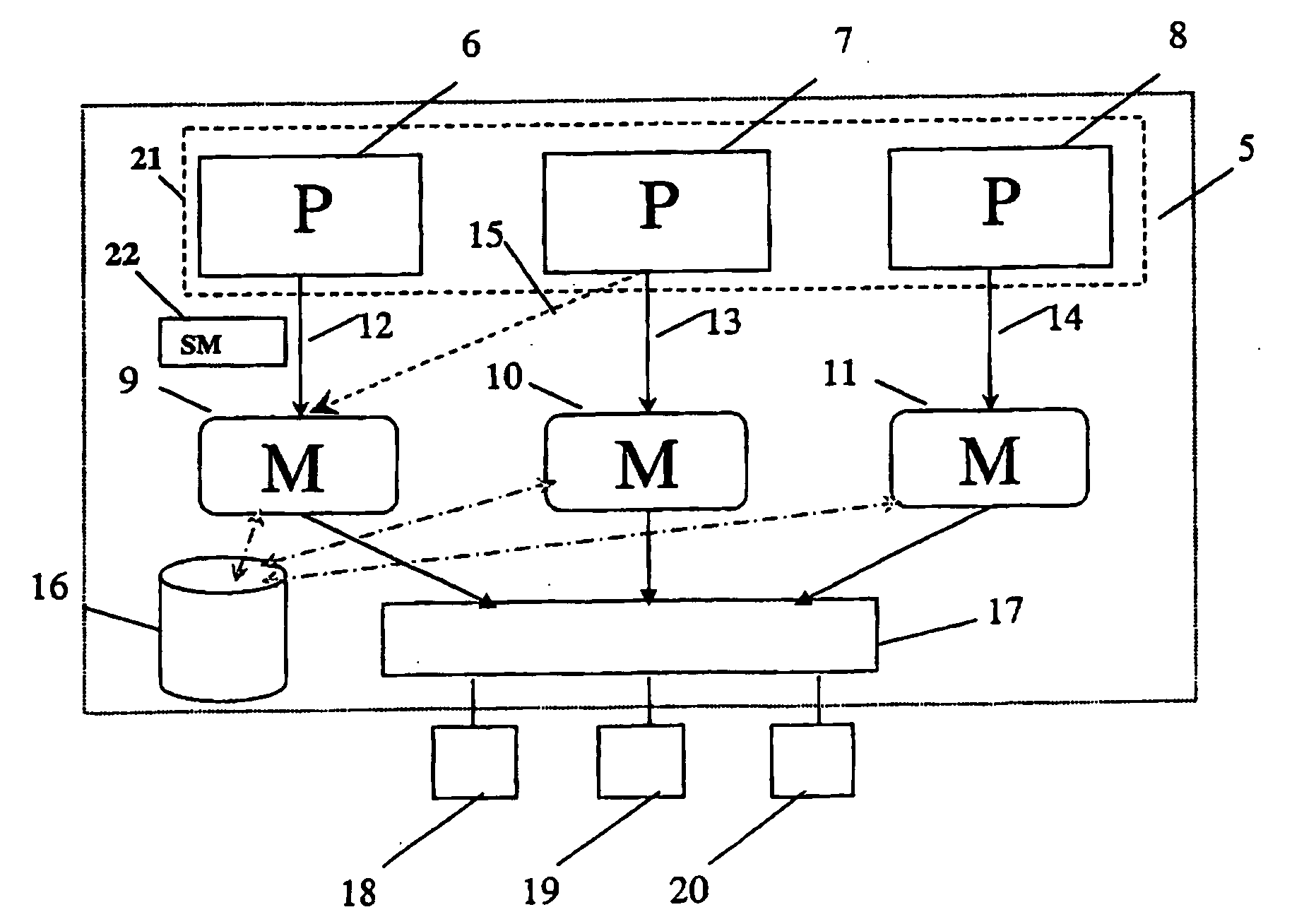
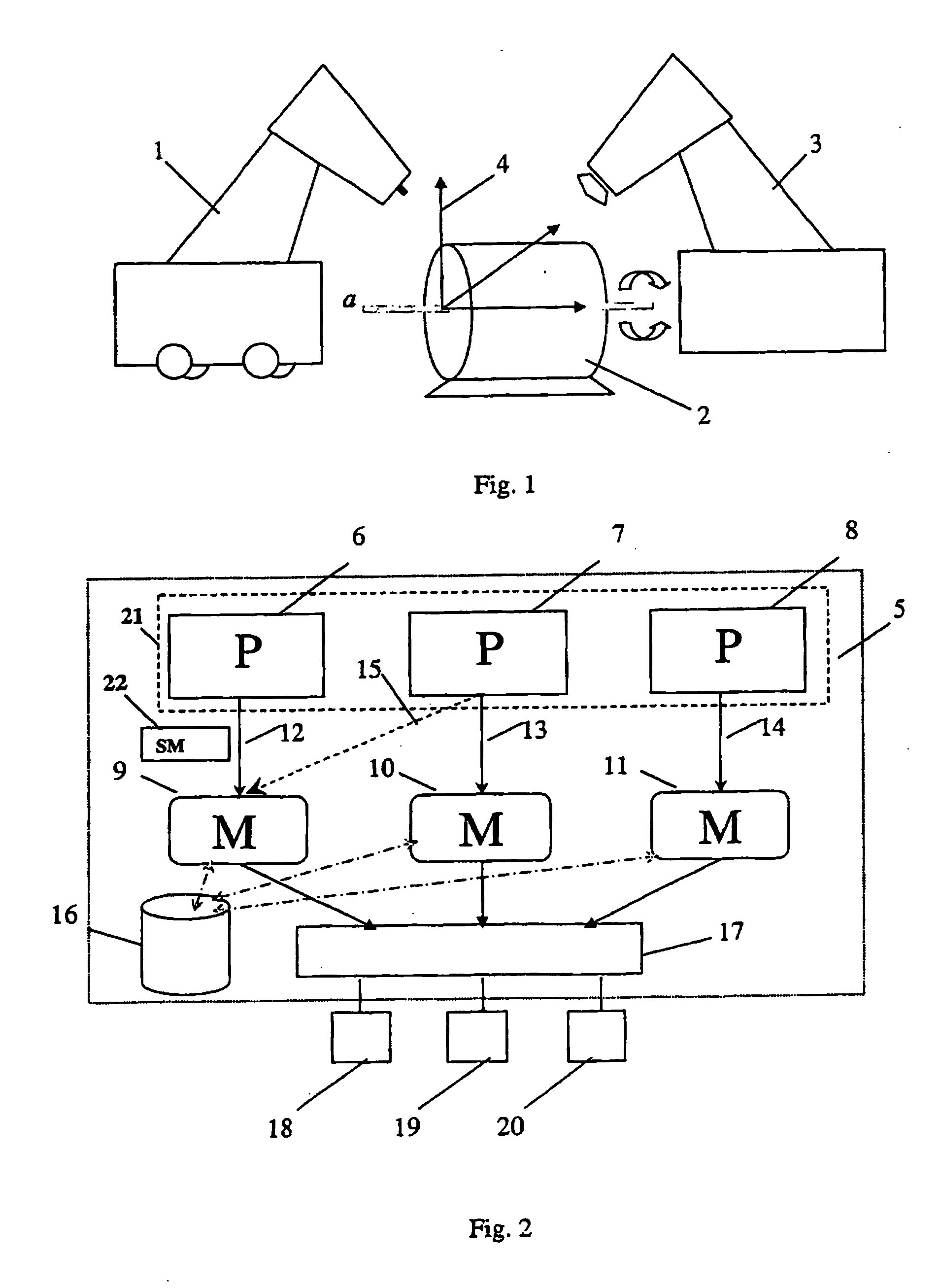
[0019]According to an embodiment of the invention the control system comprises a central data storage means and at least one mechanical unit is arranged to transmit data concerning its position, such as robot arm position, its joint angles or the orientation of a tool mounted on the robot, and / or status, i.e. operating state, to the central data storage means. The position data is given either as an absolute position with reference to a world coordinate system for example, or a relative position with respect to the mechanical unit's previous position. This embodiment enables easy access to information concerning the mechanical units in the system so that the other mechanical units in the system knows exactly what the other mechanical units are doing.
[0020]This means that the information concerning the position and status of at least one, or all of the mechanical units or parts thereof, is easily accessible and that it is possible to see which program and / or which part of a program a mechanical unit is executing. The control system therefore provides updated information on the position and status at least one or all of the mechanical units on request from a mechanical-unit-program, a path planner or an operator who is monitoring the system or who is programming one of the system's mechanical units. A mechanical-unit-program does not therefore have to be modified when one of the mechanical units moves. Such a system enables a robot to find an object located on a stationary manipulator, for example, even if the manipulator's location has changed since the robot's program was written. Furthermore, the position and status data for every mechanical unit is accessible by every other mechanical unit in the system so each mechanical unit can find out exactly what the other mechanical units are doing even if all of the mechanical units are running independently.

Problems solved by technology

If movement instructions are provided by a single general control program, moving one robot independently of the other robots becomes impossible.
One disadvantage is that the accuracy of the synchronization is significantly reduced due to delays in the transmission of data from the master to the slaves, and due to the fact that each movement is planned separately without considering possible limitations of the other mechanical units.

Method used


Image

  • Control System, Method and Computer Program For Synchronizing Several Robots
  • Control System, Method and Computer Program For Synchronizing Several Robots

Examples


Embodiment Construction

[0033]FIG. 1 shows a two-robot system comprising two robots 1, 3 and an external axis 2, such as a workstation that conveys and positions workpieces mounted thereon. The external axis 2 rotates about an axis, a. Robot 1 is a welding robot mounted on a mobile base. Mounting a robot on a mobile base extends the reach of the robot arm and increases the size of the robot workspace. The additional degrees of freedom in the mobility of the mechanical unit are however not a problem if a control system according to the present invention is used to control the mobile mechanical unit. The additional degrees of freedom are in fact turned to advantage by using them to accomplish additional tasks specified by an operator.

[0034]Robot 3 is mounted on a stationary base and comprises a tool, such as a welding gun, mounted on the robot to execute specified work on workpieces mounted on the rotatable external axis 2. The workpieces on the external axis 2 are moved during the welding and their location...


PUM


Abstract

A control system for controlling the movements of a plurality of mechanical units. The control system includes a program that includes a plurality of mechanical unit programs. Each program includes movement instructions for at least one of the mechanical units. The control system also includes a plurality of path planners. At least one of the path planners is adapted to receive instructions from more than one of the mechanical unit programs and on basis thereof determine how the mechanical units should move in order to synchronize their movements. The control system further includes switches adapted to switch a mechanical unit program from one path planner to another, whereby the movements of the mechanical units are synchronized when their mechanical unit programs are connected to the same path planner and the movements of the mechanical units are independent when their mechanical unit programs are connected to different path planners.

Description

TECHNICAL FIELD OF THE INVENTION[0001]The present invention concerns a control system for controlling the movements of a plurality of mechanical units, namely robots and external axes, such as workstations or transport tracks.[0002]The present invention also concerns a method for controlling a plurality of mechanical units and a computer program containing computer program code means for making a computer or processor execute the steps of such a method.PRIOR ART[0003]An industrial robot includes a manipulator and a control system having means for operating the manipulator. The control system comprises a storage unit for storing one or more control programs for controlling the movement of the manipulator. The control program comprises program instructions, including movement instructions for the manipulator. The control system further comprises a program executer for executing the control programs and to provide instructions based on said movement instructions, and a path planner ada...

Claims


Application Information

Patent Timeline
IPC IPC(8): G06F19/00B25JB25J9/16G05B19/418G05B19/42
CPCB25J9/1682G05B2219/39139G05B2219/39135G05B19/41815Y02P90/02
Inventor FORTELL, HAKANJOHANSSON, SVEN-ERIKLINDSTROM, SVEN-ERIK
Owner ABB (SCHWEIZ) AG
Learn More