Transmission Fluid Warming and Cooling System

a technology of transmission fluid and cooling system, which is applied in the direction of machines/engines, lighting and heating apparatus, machine operation mode, etc., can solve the problems of reduced fuel economy, inacceptable parasitic losses, and the occurrence of most automatic transmissions

Active Publication Date: 2011-11-24
FORD GLOBAL TECH LLC
View PDF11 Cites 33 Cited by
  • Summary
  • Abstract
  • Description
  • Claims
  • Application Information

AI Technical Summary

Benefits of technology

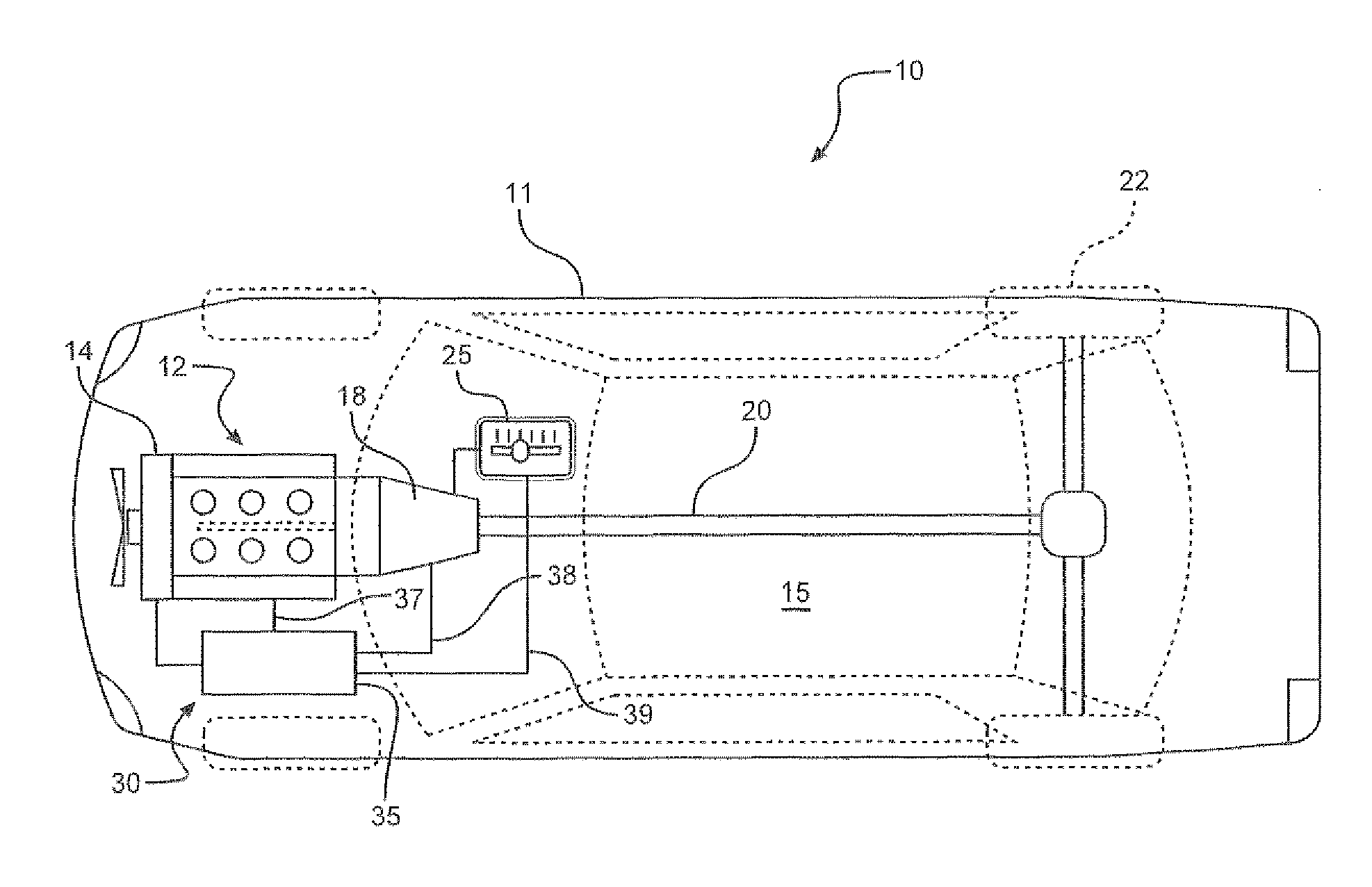
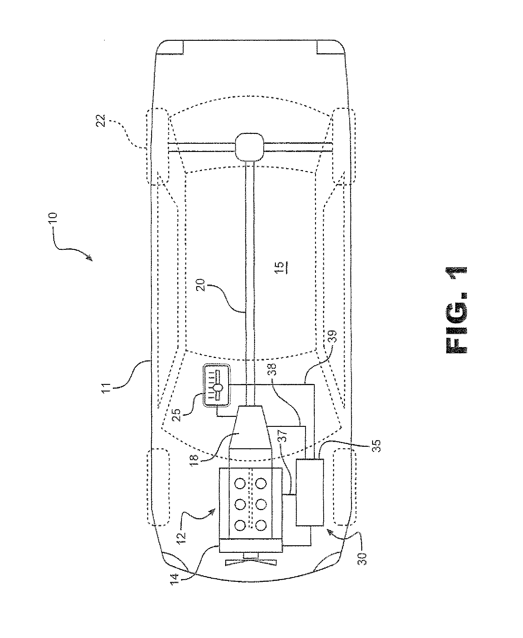
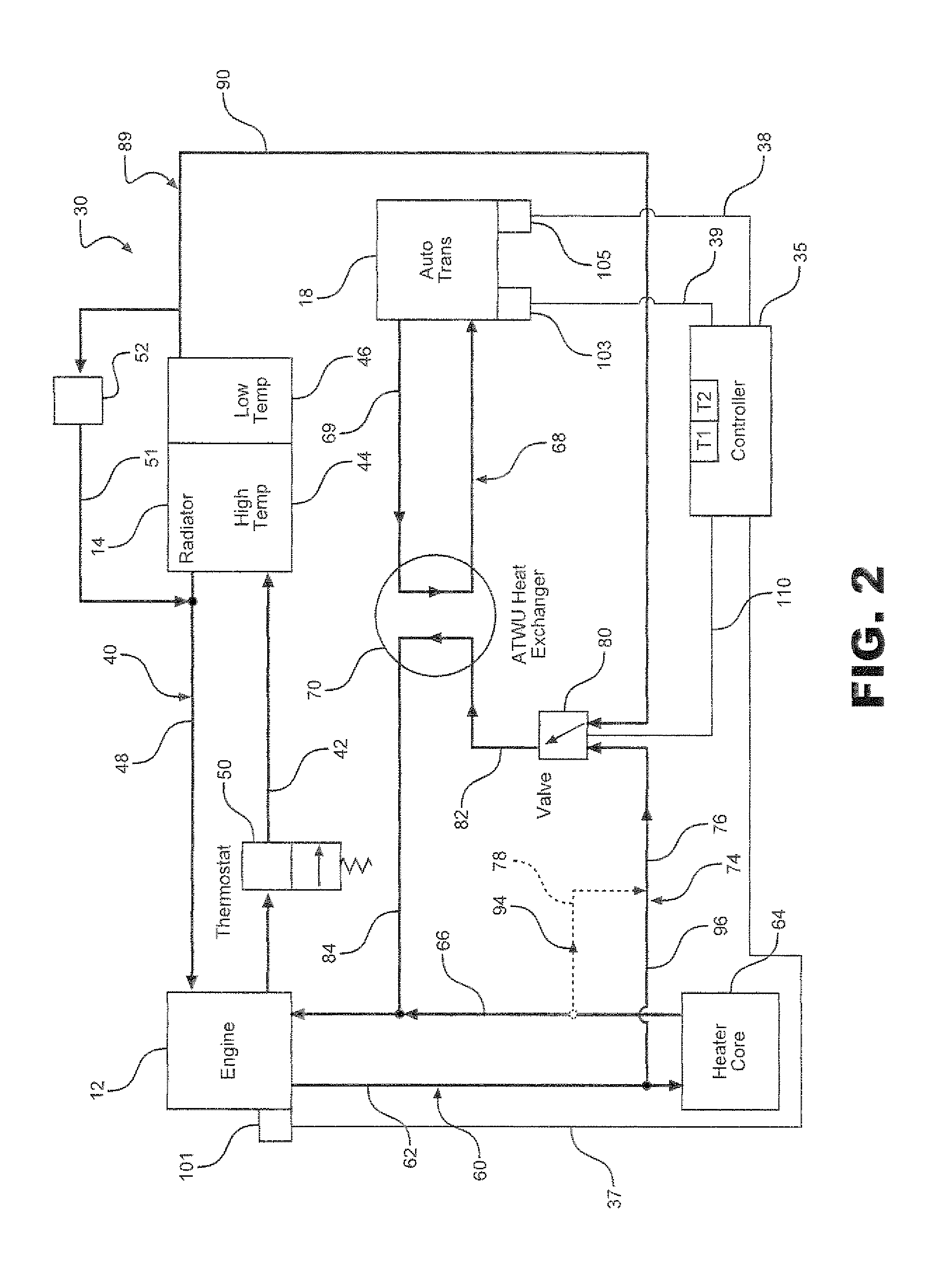
[0012]In the first preferred embodiment, the temperature of transmission fluid in the motor vehicle is preferably controlled by having the system selectively enter a heater priority mode, an automatic transmission fluid heating mode or an automatic transmission fluid cooling mode. The system enters the automatic transmission fluid heating mode by sending hot engine coolant to the heat exchanger for heating the automatic transmission fluid by transferring heat from the hot engine coolant to the automatic transmission fluid. The system enters the automatic transmission fluid cooling mode by sending cold engine coolant to the heat exchanger for cooling the automatic transmission fluid by transferring heat from the automatic transmission fluid to the cold engine coolant. The system enters the heater priority when the valve is positioned to receive cold engine coolant before the engine thermostat opens. This heater priority mode is only available for a relatively short period of time prior to when the engine warms up. The system switches between the modes based on a sensed temperature by using the valve to selectively provide either hot engine coolant from the engine or cold coolant from the radiator.

Problems solved by technology

Unfortunately, most automatic transmissions typically suffer from parasitic losses on startup of the power source.
Since the automatic transmission fluid present in the transmission has a viscosity that changes based on temperature, in cold temperature the viscosity may be quite high, thereby causing unacceptable parasitic losses and reduced fuel economy at least until the power source warms up the transmission and the automatic transmission fluid.
Another problem associated with controlling the temperature of automatic transmission fluid is overheating.
When a motor vehicle is subject to heavy use, for example, when the motor vehicle is towing a heavy load, the automatic transmission fluid is often heated too quickly and may overcome inherent cooling present in the transmission and additional cooling systems must be employed.
However, in past arrangements, additional cooling has been required and therefore the arrangements have not been cost effective.
Also, such arrangements have adversely affected passenger compartment heating and even adversely affected coolant flow through associated radiators.
However, such an arrangement still suffers from several drawbacks.
For example, the arrangement employs an excessive number of parts, which form a complex system that is slow to respond to changes in temperature.
Furthermore, in order to function properly, the arrangement in FIG. 2 requires a relatively large number of control valves and heat exchangers yielding a relatively complicated and expensive system.

Method used


Image

  • Transmission Fluid Warming and Cooling System
  • Transmission Fluid Warming and Cooling System
  • Transmission Fluid Warming and Cooling System

Examples


second embodiment

[0039]Turning to FIGS. 5-7, there is shown a second preferred embodiment of the invention. Most of the parts of the second preferred embodiment are the same as the first preferred embodiment and like reference numerals are used for like parts. Only the differences between the two embodiments will be discussed here. In the second preferred embodiment, a system 130 has a transmission cooling circuit 189 with a second valve 190 not found in the first preferred embodiment. Second valve 190 is connected to an engine coolant supply line 192. Second valve 190 is controlled by controller 35 through communication line 195 and is adapted to switch flow between a cold-coolant return conduit 198 and coolant line 192. Second valve 190 is positioned to selectively send cold engine coolant flow 199 back to engine12 as in FIGS. 5 and 6, or to send cold engine coolant to valve 80 as in FIG. 7 to place system 130 in a transmission cooling mode. When second valve 190 sends fluid back to engine 12, sys...

first embodiment

[0041]Turning now to FIGS. 11-13, there is shown a fourth preferred embodiment of the invention. Most of the parts of the fourth preferred embodiment are the same as the third preferred embodiment and like reference numerals are used for like parts. Only the differences between the two embodiments will be discussed here. Specifically, valve 190 of the third preferred embodiment has been replaced with valve 290 which is set to either allow or not allow flow from radiator 14 to heat exchanger 70. Additionally, return conduit 198 is not used but rather return line 51 and restriction device 52 from the first embodiment are used. Valves 280 and 290 are closed in FIG. 11 thus placing a system 330 into a heater priority mode. In FIG. 12, system 330 is in an automatic transmission fluid heating mode with a hot engine coolant flow passing through heat exchanger 70 because first valve 280 is open allowing the flow of hot engine coolant from engine 12 through line 76, while valve 290 is set to...


PUM


Abstract

A system for heating and cooling the transmission fluid including a heat exchanger adapted to transfer heat between an engine coolant and a transmission fluid and a controller for controlling a valve to place the system into a select one of three modes including a heater core priority mode wherein no engine coolant flows to the heat exchanger, a heating mode wherein hot engine coolant flows directly to the heat exchanger from the engine and a cooling mode wherein cool engine coolant flows directly to the heat exchanger from the radiator, whereby the transmission fluid is heated in an efficient manner with minimal impact on passenger compartment heating.

Description

FIELD OF THE INVENTION[0001]The present invention pertains to the art of reducing parasitic losses in transmissions by warming up transmission fluid present in the transmission in a rapid and efficient manner thereby reducing the transmission fluid's viscosity and cooling the transmission fluid when the transmission is subject to heavy loads.BACKGROUND OF INVENTION[0002]Motor vehicles are typically used to transport people from place to place. As such they often have a passenger compartment and a power source, such as an engine that drives an automatic transmission which transmits energy from the power source to a set of driven wheels to propel the vehicle. Making such motor vehicles more efficient is currently a main focus of the automobile industry. Unfortunately, most automatic transmissions typically suffer from parasitic losses on startup of the power source. Such losses are particularly acute in the presence of low ambient temperatures, such as those present in a cold start in...

Claims


Application Information

Patent Timeline
Patent Type & Authority Applications(United States)
IPC IPC(8): F16H57/04B60H1/00
CPCB60H1/14F01P7/16F01P2037/02F01P2060/045Y10T477/653F16H57/0413F16H57/0417F16H57/0475F01P2060/08
Inventor GOODEN, JAMES THOMASMACWILLSON, HAMISHILIESCU, DRAGOS CATALIN
Owner FORD GLOBAL TECH LLC
Why Eureka
Try Eureka