Induction machine bearing system

Active Publication Date: 2011-11-24
SIEMENS IND INC
View PDF9 Cites 14 Cited by
  • Summary
  • Abstract
  • Description
  • Claims
  • Application Information

AI Technical Summary

Benefits of technology

[0010]It is another independent object of the invention to provide an induction machine bearing system employing both magnetic and auxiliary bearings that reduces potential for impact shock to the magnetic bearing structure upon magnetic bearing failure, by transferring and/or such shock forces away from the magnetic bearing structure to other structural components within the machine.
[0011]It is yet another independent object of the invention to provide an induction machine bearing system employing both magnetic and auxiliary bearings that enables easy servicing of the auxiliary bearing.
[0012]These and other objects are achieved in accordance with the present invention by the induction machine bearing system of the present invention. A bearing assembly of the present invention, for an induction machine such as an alternating current motor, includes a bearing support collar coupled to the

Problems solved by technology

Upon magnetic bearing operational failure, motor shaft mechanical forces are transferred rapidly to the auxiliary beari

Method used


Image

  • Induction machine bearing system
  • Induction machine bearing system
  • Induction machine bearing system

Examples


Embodiment Construction

[0023]After considering the following description, those skilled in the art will clearly realize that the teachings of my invention can be readily utilized in induction machine bearing systems, including those for AC motors. While the present invention may be applied to various types of induction machines, the remainder of this description will focus on an exemplary application to AC motors.

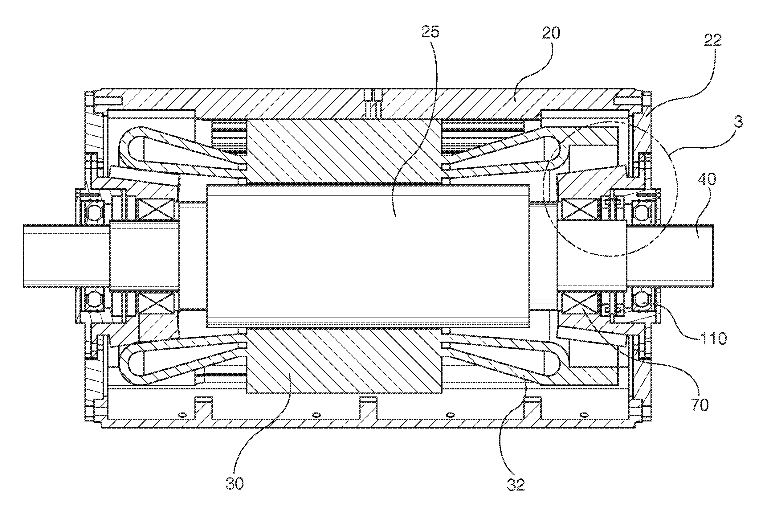
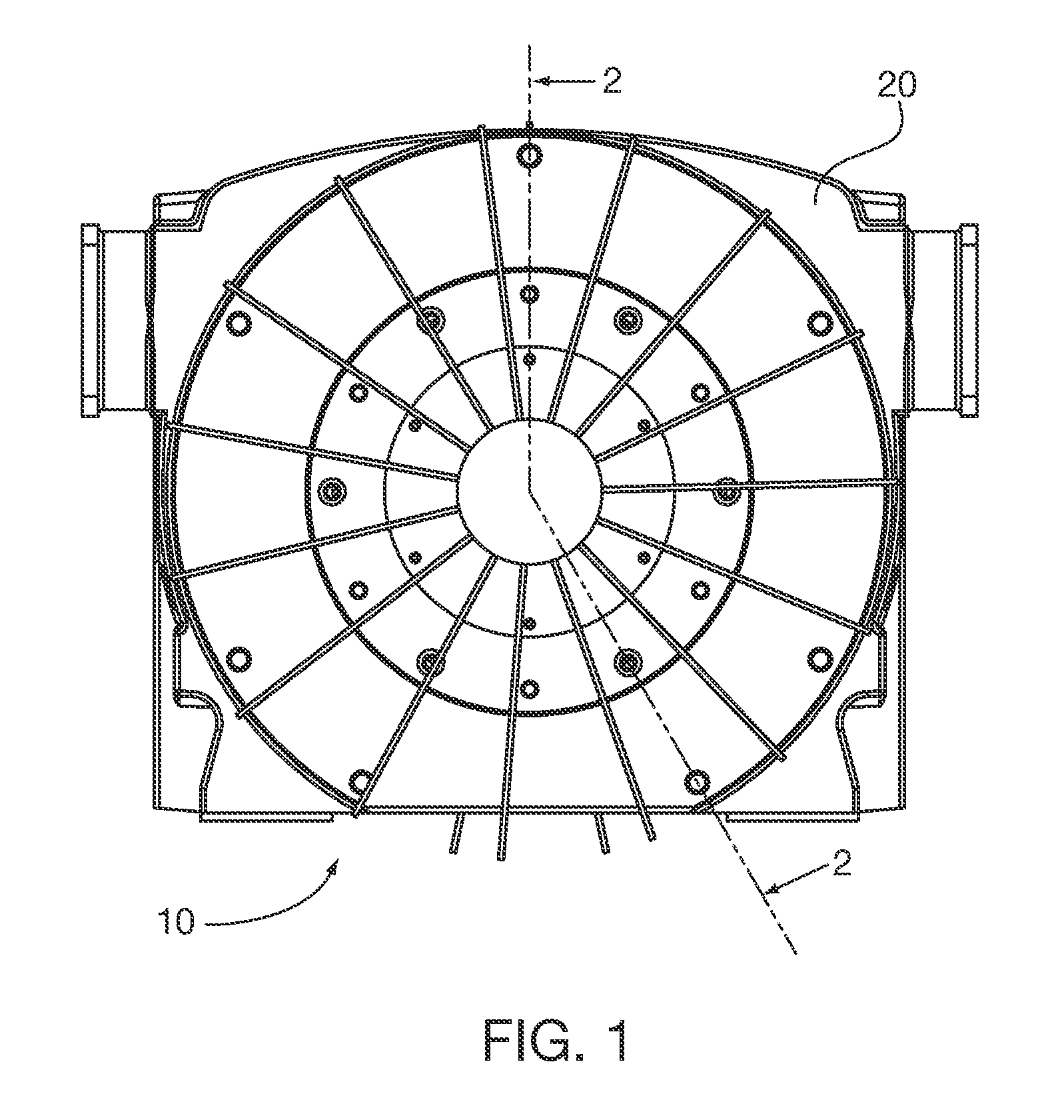
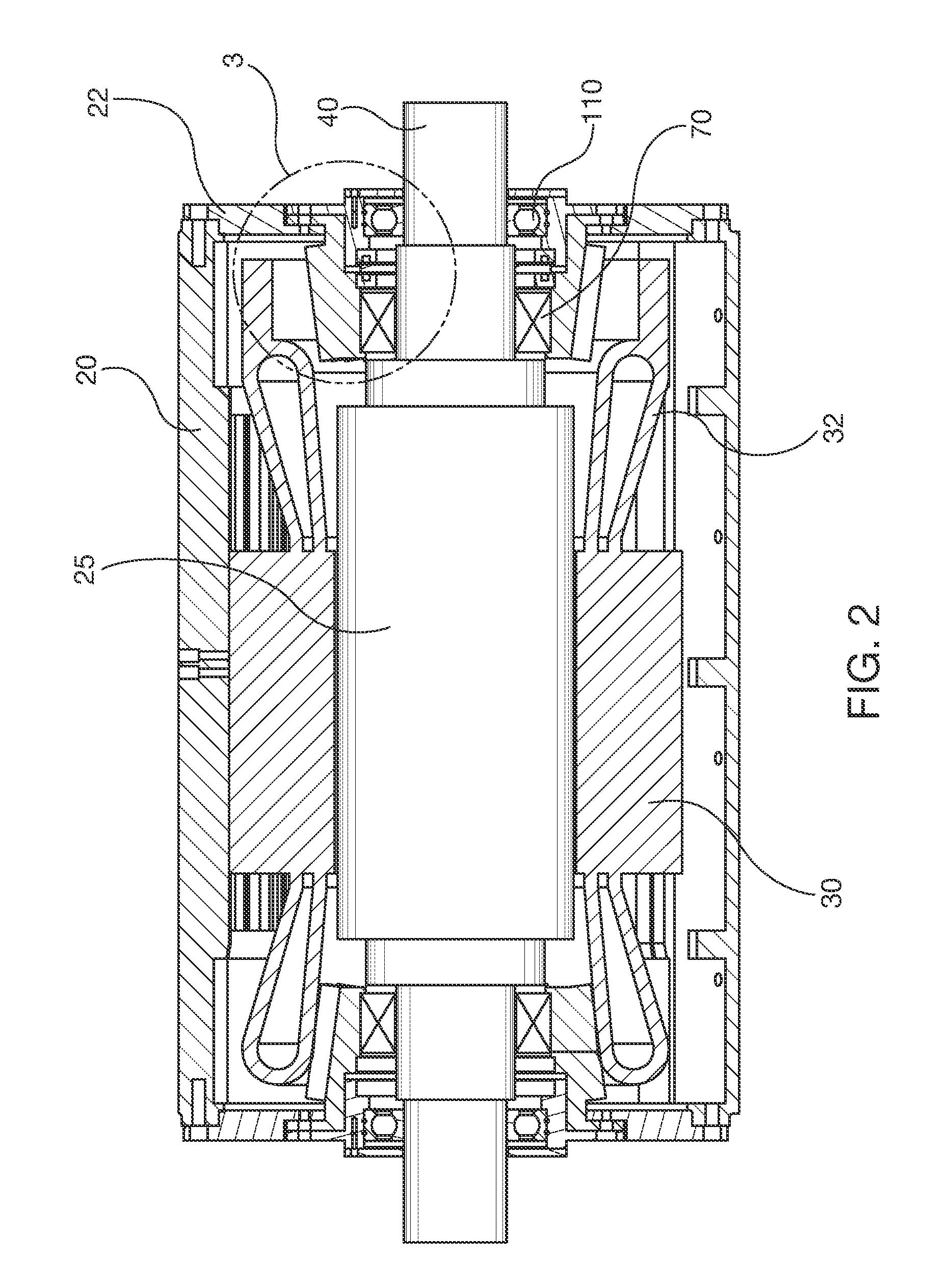
[0024]FIGS. 1 and 2 show generally an AC motor 10 having a motor frame 20 and a frame end shield 22. Electromotive mechanical work is generated by electromagnetic interaction of the rotor laminations 25 and stator coils 30, shown in an exemplary known squirrel cage configuration. The stator coils 30 have end coils 32, of known construction. Rotor laminations are coupled to shaft 40, all of known construction.

[0025]Shaft 40 is rotatively mounted in at least one or more bearing assemblies 50. Referring to FIGS. 3-6, the bearing assembly 50 has a bearing support collar 60 with a mounting flange 61 t...


PUM


Abstract

A bearing assembly for an induction machine, such as an alternating current motor, includes a magnetic bearing for supporting a rotating shaft. An auxiliary bearing, also supporting the shaft in the event of magnetic bearing failure, is aligned with the motor end shield and frame so that shaft loads supported thereby are transferred to the frame in a manner that reduces likelihood of magnetic bearing contact with the shaft or its deformation. The bearing assembly may incorporate shock absorbing and vibration damping/isolation elements, such as o-rings, between the auxiliary bearing and its support structure interface to the frame. The auxiliary bearing may be incorporated in a removable cartridge for ease of machine maintenance. The bearing assembly may include heat dissipating fins.

Description

BACKGROUND OF THE DISCLOSURE[0001]1. Field of the Invention[0002]The invention relates to induction machine bearing systems, and more particularly to electric motor bearing systems including an active magnetic bearing and an auxiliary mechanical bearing, both supporting a rotatable shaft.[0003]2. Description of the Prior Art[0004]Induction machines, such as alternating current (AC) electric motors incorporate rotating shafts supported by bearings. Traditionally, motor bearings have included mechanical hydrostatic and hydrodynamic fluid film bearings and rolling element bearings.[0005]In the more recent past, some induction machines have incorporated contactless magnetic bearings. An exemplary magnetic bearing is shown in U.S. Pat. No. 6,777,841. As is known in the art, magnetic bearings enable higher rotational speeds above traditional 50 / 60 Hz excitation frequencies, higher torque outputs and active shaft vibration damping: thereby enabling direct drive of compressors and other dri...

Claims


Application Information

Patent Timeline
IPC IPC(8): H02K7/09
CPCF16C35/00F16C39/02H02K5/1732F16C32/047H02K7/09F16C32/0442H02K7/083F16C2380/26
Inventor SINGHAL, SUMITSTENGEL, T.J.
Owner SIEMENS IND INC
Why Eureka
Try Eureka