
Eureka
For R&D, Eureka makes reading and utilizing patents & technical documents easy.
Eureka AIR
Designed for self-driven R&D workflows. Generate viable solutions, solve complex R&D challenges, empower your innovation with AI.

Eureka Materials
Designed for material experts only. Revolutionize your material R&D, from search, analyze, to developing new materials.

TechResearch
Generate reliable direction feasibility study reports for your R&D in just a few steps.

TechSeek
Discover and master advanced knowledge NOW. Basics, ideas, possibilities, all at once.

TechMind
As an expert in R&D Theories, TechMind can generates customized viable solutions instantly.

TechRisk
Analyze your overall solution with one click, know your potential R&D risks in advance.

TechMonitor
Get weekly tech updates, stay abreast of the latest tech innovations and key insights.
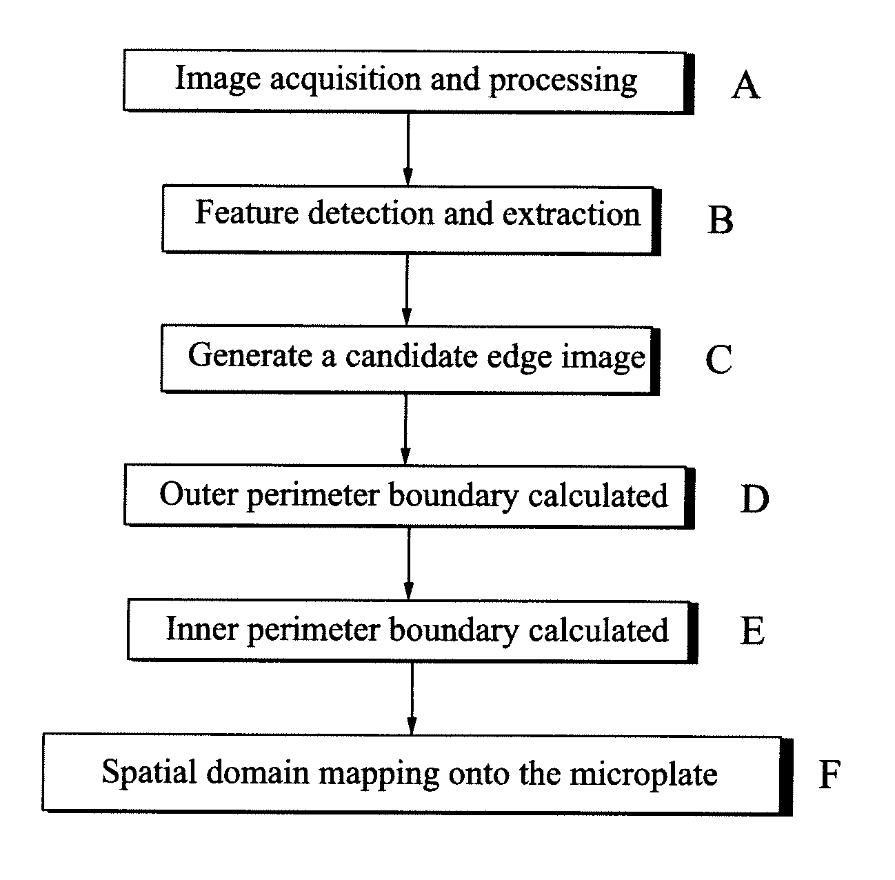
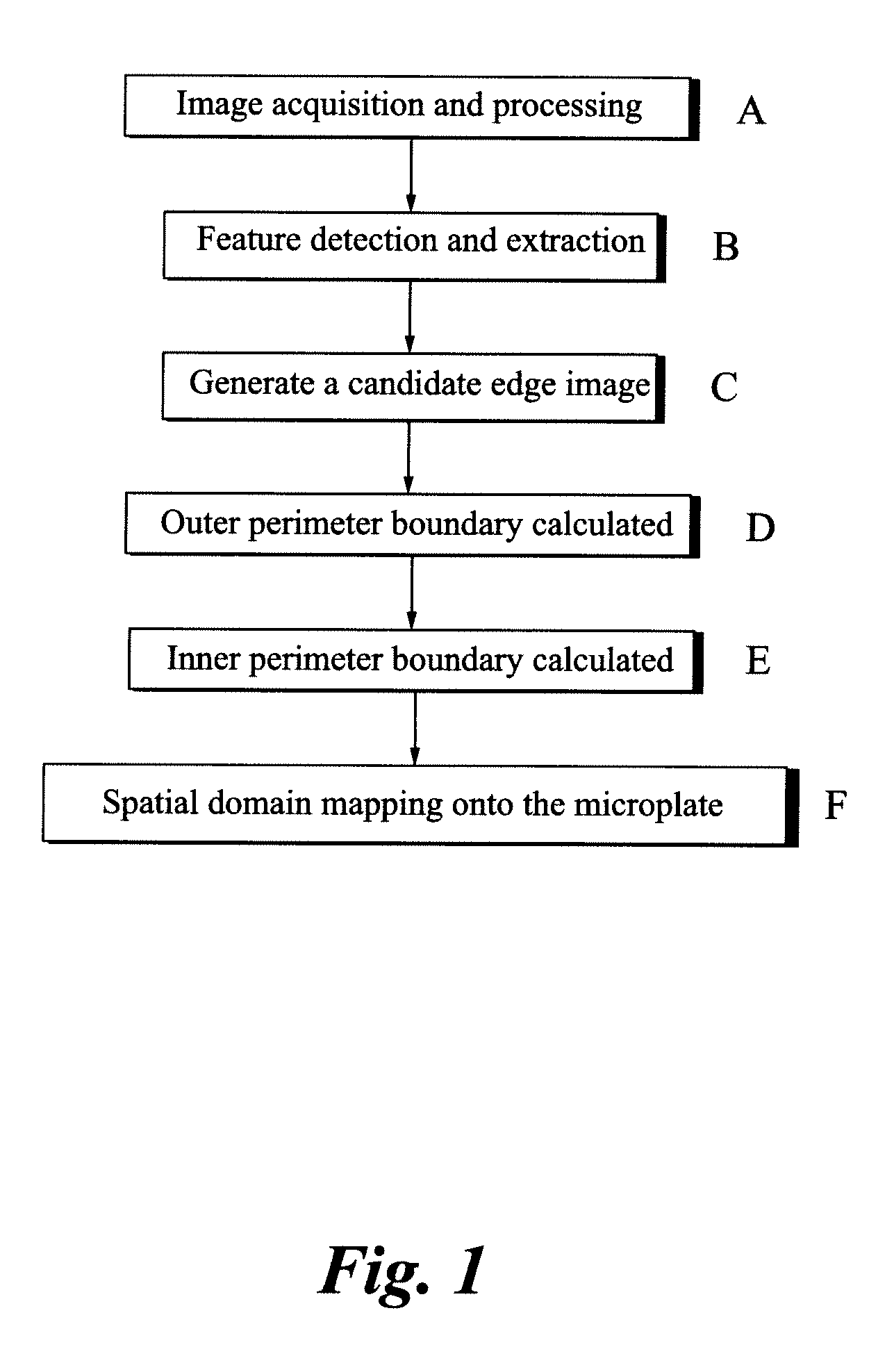
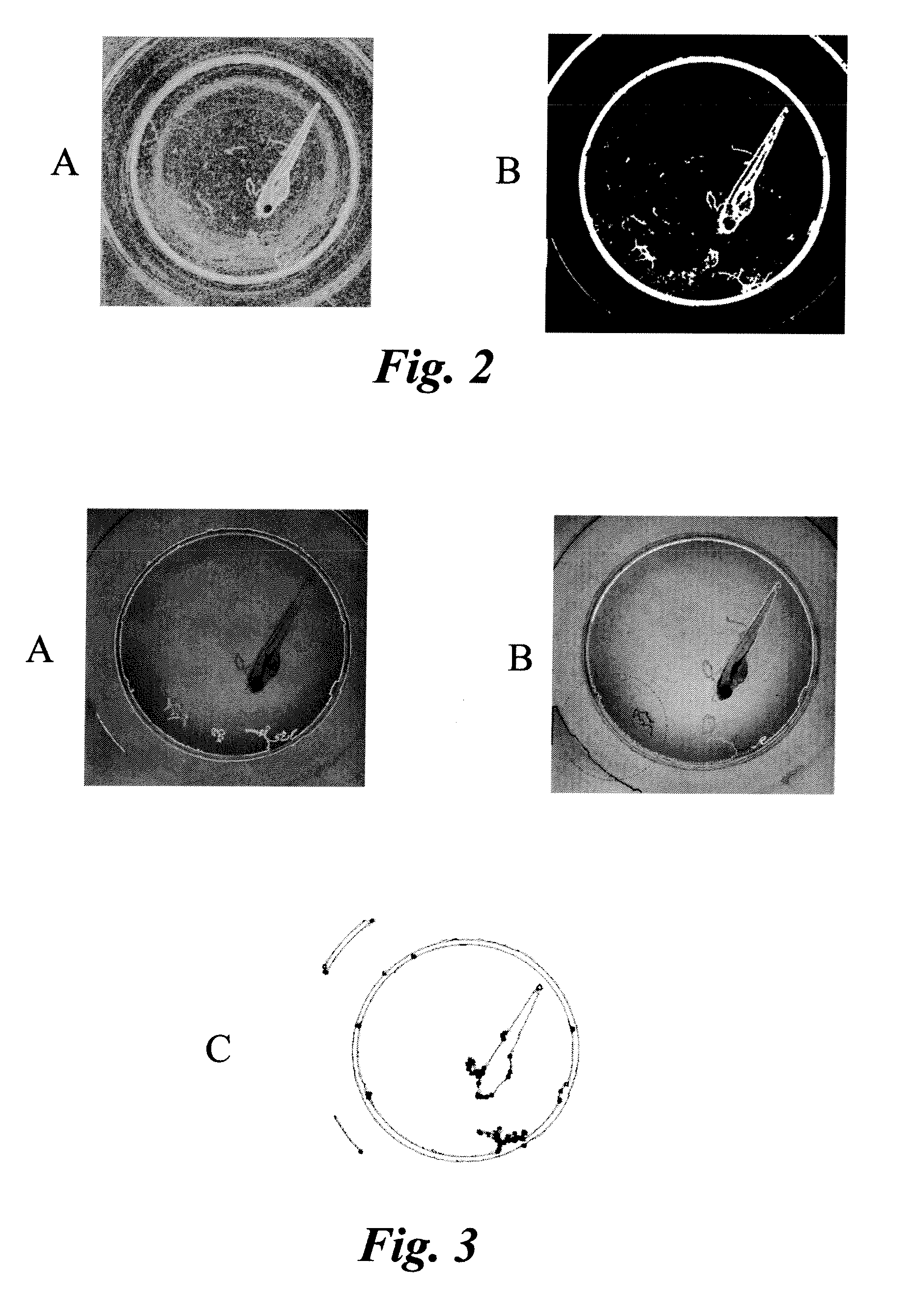
Methods and systems for identifying well wall boundaries of microplates
- Summary
- Abstract
- Description
- Claims
- Application Information
AI Technical Summary
Benefits of technology
Problems solved by technology
Method used
Image

Examples
Embodiment Construction
[0014]In the following specification and the claims, which follow, reference will be made to a number of terms, which shall be defined to have the following meanings.
[0015]The singular forms “a”, “an” and “the” include plural referents unless the context clearly dictates otherwise.
[0016]“Samples” refer to the chemical or biological test materials, which are contained within the test wells of the microplate. The samples may be cell and tissue cultures as well as whole organisms such as the zebrafish. A test well may also contain one or more samples such as multiple organisms. Common detection modes include, but are not limited to, absorbance, fluorescence intensity, luminescence, time-resolved fluorescence, and fluorescence polarization.
[0017]The tissue sample may also be part of a tissue microarray (TMA). As such the tissue sample is one of multiple samples contained within test wells arranged on a single slide. The number of test wells, and therefore the number of individual tissue...
PUM
 Abstract
Description
Claims
Application Information
 - R&D Engineer
- R&D Manager
- IP Professional
- Industry Leading Data Capabilities
- Powerful AI technology
- Patent DNA Extraction
Browse by: Latest US Patents, China's latest patents, Technical Efficacy Thesaurus, Application Domain, Technology Topic, Popular Technical Reports.
© 2024 PatSnap. All rights reserved.Legal|Privacy policy|Modern Slavery Act Transparency Statement|Sitemap|About US| Contact US: help@patsnap.com