
Wet-processing apparatus

a technology of wet processing and wet-processing equipment, which is applied in the direction of optics, instruments, photosensitive materials, etc., can solve the problems of difficult decision-making of this technique, and achieve the effects of improving accuracy, high brightness, and stably conspicuous

Active Publication Date: 2011-11-24
TOKYO ELECTRON LTD
View PDF5 Cites 49 Cited by
  • Summary
  • Abstract
  • Description
  • Claims
  • Application Information

AI Technical Summary

Benefits of technology

[0010]The present invention has been made under such circumstances and it is therefore an object of the present invention to provide a wet-processing apparatus capable of accurately deciding whether or not the coating liquid was spouted from the nozzle and whether or not changes occurred in the condition of the coating liquid spouted from the nozzle toward a substrate.
[0035]The wet-processing apparatus of the present invention can accurately decide whether or not the processing liquid was spouted from the processing nozzle spouting nozzle and whether or not changes occurred in the condition of the processing liquid spouted from the processing liquid spouting nozzle.

Problems solved by technology

Therefore, it is difficult for this technique to decide whether or not the coating liquid was spouted from the nozzle and whether or not changes occurred in the condition of the coating liquid spouted from the nozzle onto a substrate, such as bubbling resulting from inclusion of gas in the coating liquid and the narrowing of a column of the spouted coating liquid, occurred at an early stage.

Method used


Image

  • Wet-processing apparatus
  • Wet-processing apparatus
  • Wet-processing apparatus

Examples


first embodiment

[0057]A coating unit as a first embodiment of a wet-processing apparatus according to the present invention will be described.

[0058]The coating unit applies a resist solution, namely, a processing liquid, namely, a substrate, and a thinner for facilitating the spread of the resist solution over the surface of a wafer W to the surface of the wafer W. In the following description, the resist solutions and the thinner will be designated inclusively as a coating liquid R. The outline of the construction of the coating unit will be described.

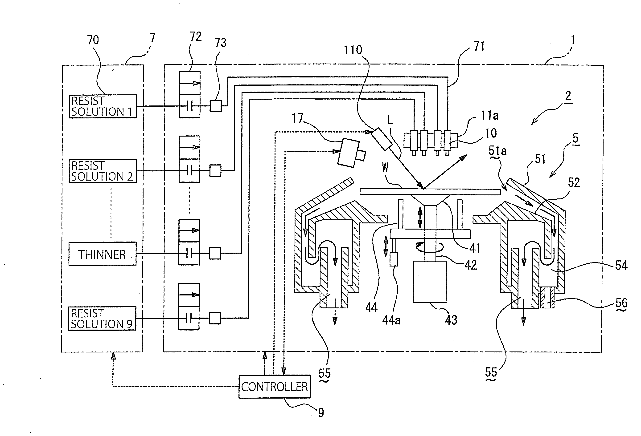
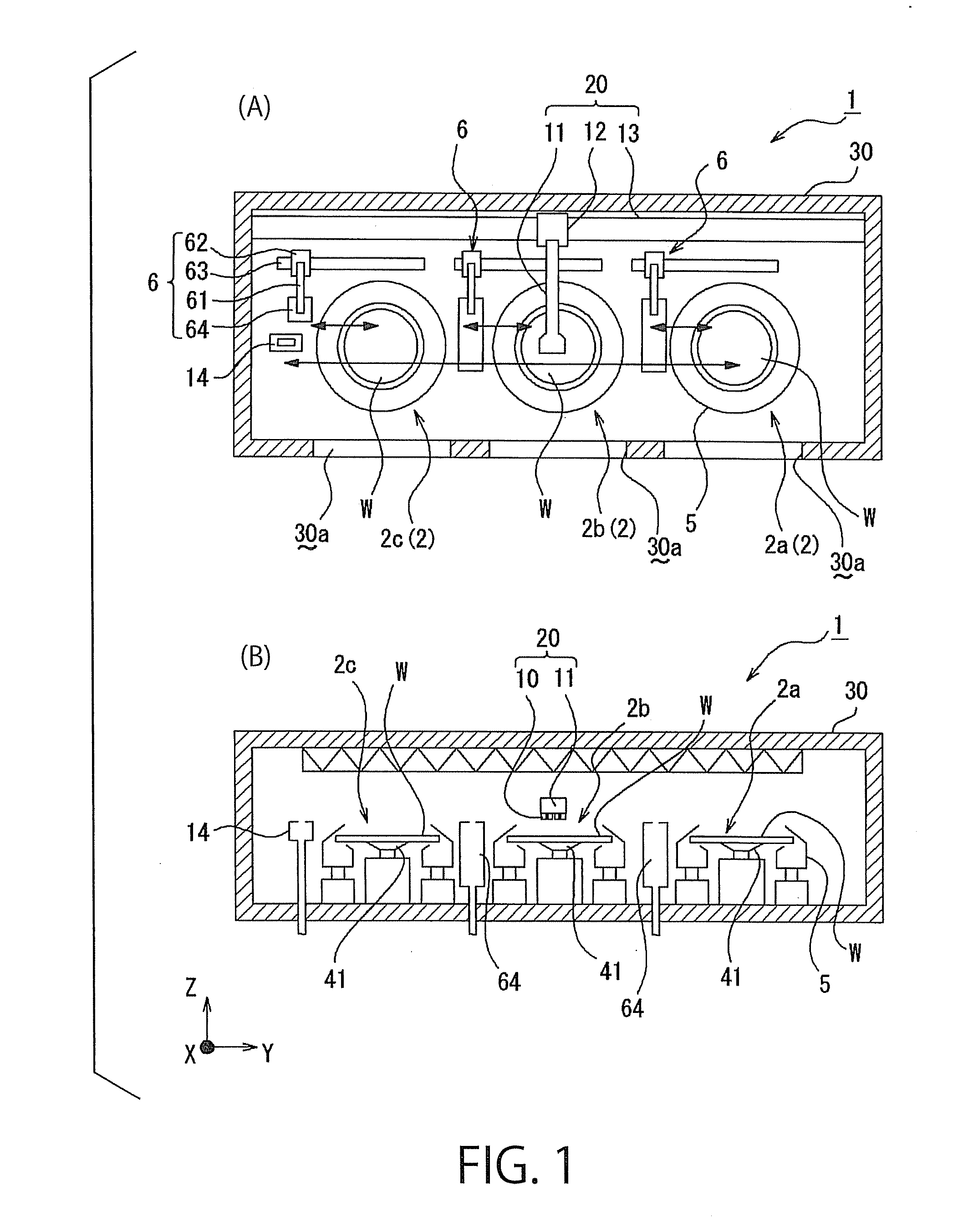
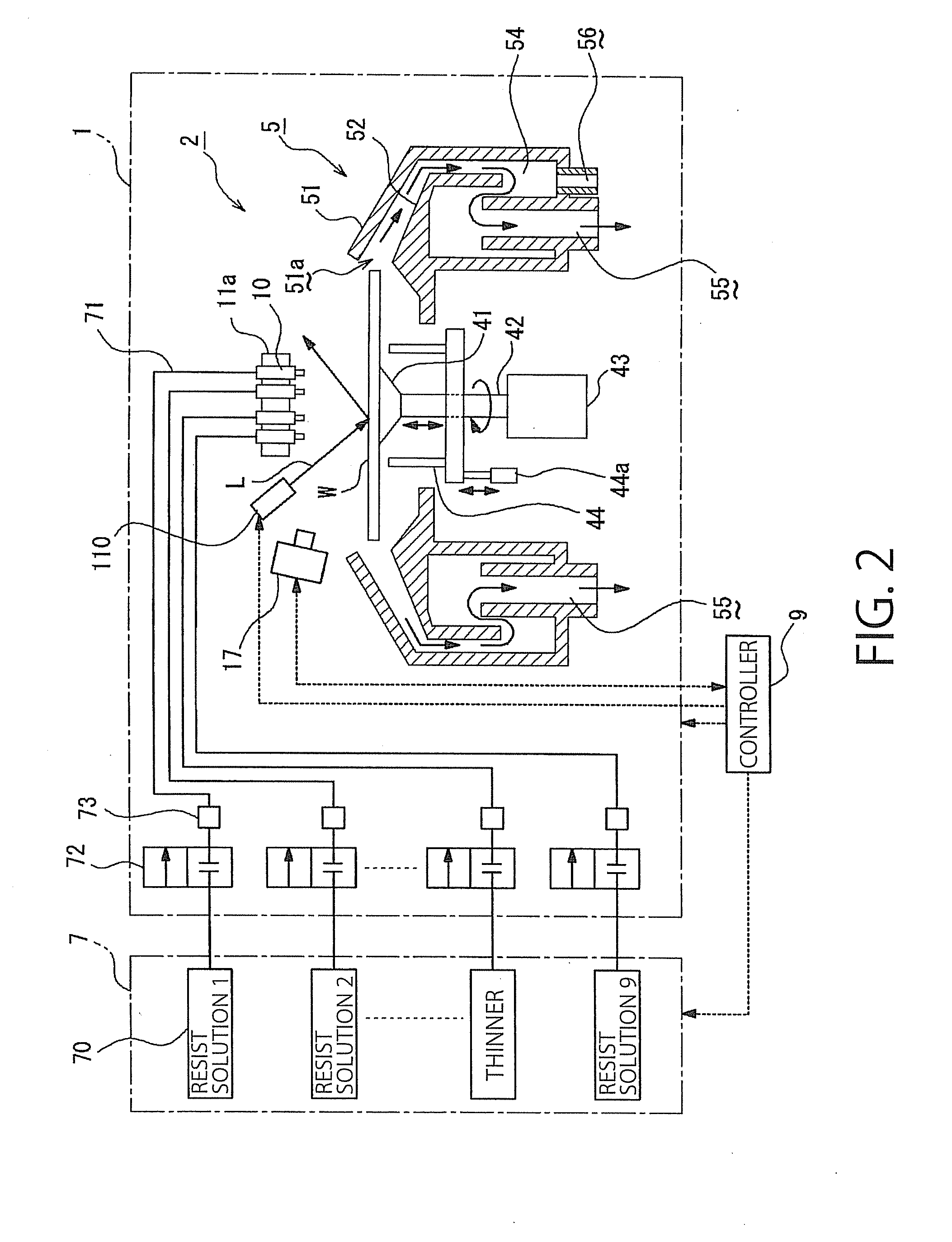
[0059]Referring to FIG. 1, a coating unit 1 in a first embodiment according to the present invention has three wet-processing devices 2a, 2b and 2c arranged in a lateral row parallel to the Y-axis in a box-shaped housing 30, a plurality of processing liquid spouting nozzles 10 (hereinafter referred to simply as “nozzles 10”), for supplying the coating liquids R, such as a resist solution and thinner, to the wet-processing devices 2a, 2b and 2c, a noz...

second embodiment

[0124]In the coating unit 1 in the first embodiment, the laser beam L is projected into the area between the plane containing the tips 10d of the nozzles 10 and the surface W1 of the wafer W. An infrared emitter 111 may emit infrared radiations I toward the area between a plane containing the tips 10d of the nozzles 10 and the surface W1 of the wafer W and toward the nozzles 10 as shown in FIG. 10, and the decision unit 9b may measure, in addition to measuring the brightness of the coating liquid R illuminated by the rays penetrated into and reflected by the coating liquid R to decide whether or not the coating liquid R was spouted from the nozzle 10 and whether or not changes occurred in the condition of the coating liquid R spouted from the nozzle 10, the brightness of the coating liquid R in the passage 10e of the nozzle 10 to decide whether or not the level of the coating liquid R in the passage 10e changed.

[0125]A coating unit in the second embodiment, includes the infrared emi...


PUM


Abstract

A wet-processing apparatus, which spouts a coating liquid onto a surface of a substrate of a substrate, includes: nozzles provided with passages for the coating liquid; a light source which illuminates an area between a plane containing the tips of the nozzles and the surface of the substrate; a camera for forming an image of the area; a control unit which provides a spout signal requesting spouting the liquid from the nozzle toward the substrate, and an imaging signal requesting the camera to start an imaging operation; and a decision unit which decides whether or not the liquid was spouted from the nozzle and whether or not changes occurred in the condition of the liquid spouted from the nozzle toward the substrate on the basis of an image formed by the camera and expressing the brightness of the liquid spouted toward the substrate and illuminated by light emitted by the light source.

Description

BACKGROUND OF THE INVENTION[0001]1. Technical Field[0002]The present invention relates to a wet-processing apparatus which processes substrates, such as semiconductor wafers or glass panels for liquid crystal displays (LCD panels), by spouting processing liquids, such as resist solutions and developers from processing liquid spouting nozzles onto substrates.[0003]2. Description of the Related Art[0004]Generally, a resist pattern forming method, namely, one of methods of fabricating semiconductor devices and LCD panels, forms a resist pattern on a substrate or a semiconductor wafer (hereinafter referred to simply as “wafer”) by a series of processes for forming a resist film on the wafer, and developing the resist film exposed through a photomask. Usually, the series of processes are carried out by a coating and developing apparatus.[0005]The coating and developing apparatus is provided with wet-processing units including coating units for resist solution application, and developing ...

Claims


Application Information

Patent Timeline
IPC IPC(8): G03D5/00
CPCH01L21/67253H01L21/6715G03F7/16H01L21/0274
Inventor NODA, YASUAKIFUKUTOMI, AKIRAHAYAMA, TAKAFUMI
Owner TOKYO ELECTRON LTD
Features
  • Generate Ideas
  • Intellectual Property
  • Life Sciences
  • Materials
  • Tech Scout
  • Unparalleled Data Quality
  • Higher Quality Content
  • 60% Fewer Hallucinations
Learn More