

Method and apparatus for cooling fuel in an aircraft fuel tank
a fuel tank and fuel technology, applied in the direction of fuel tank safety measures, naca type air intakes, aircraft power plants, etc., can solve the problems of reducing engine efficiency, unable to use compressed air for cabin air conditioning, and incompatible inerting ullage, so as to reduce the flammability of fuel in the fuel tank and improve safety.
- Summary
- Abstract
- Description
- Claims
- Application Information
AI Technical Summary
Benefits of technology
Problems solved by technology
Method used
Image

Examples
first embodiment
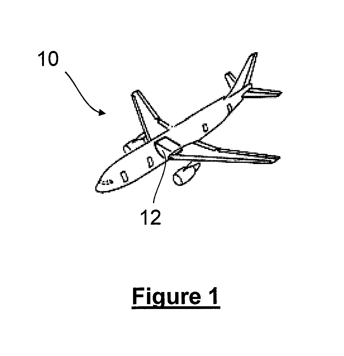
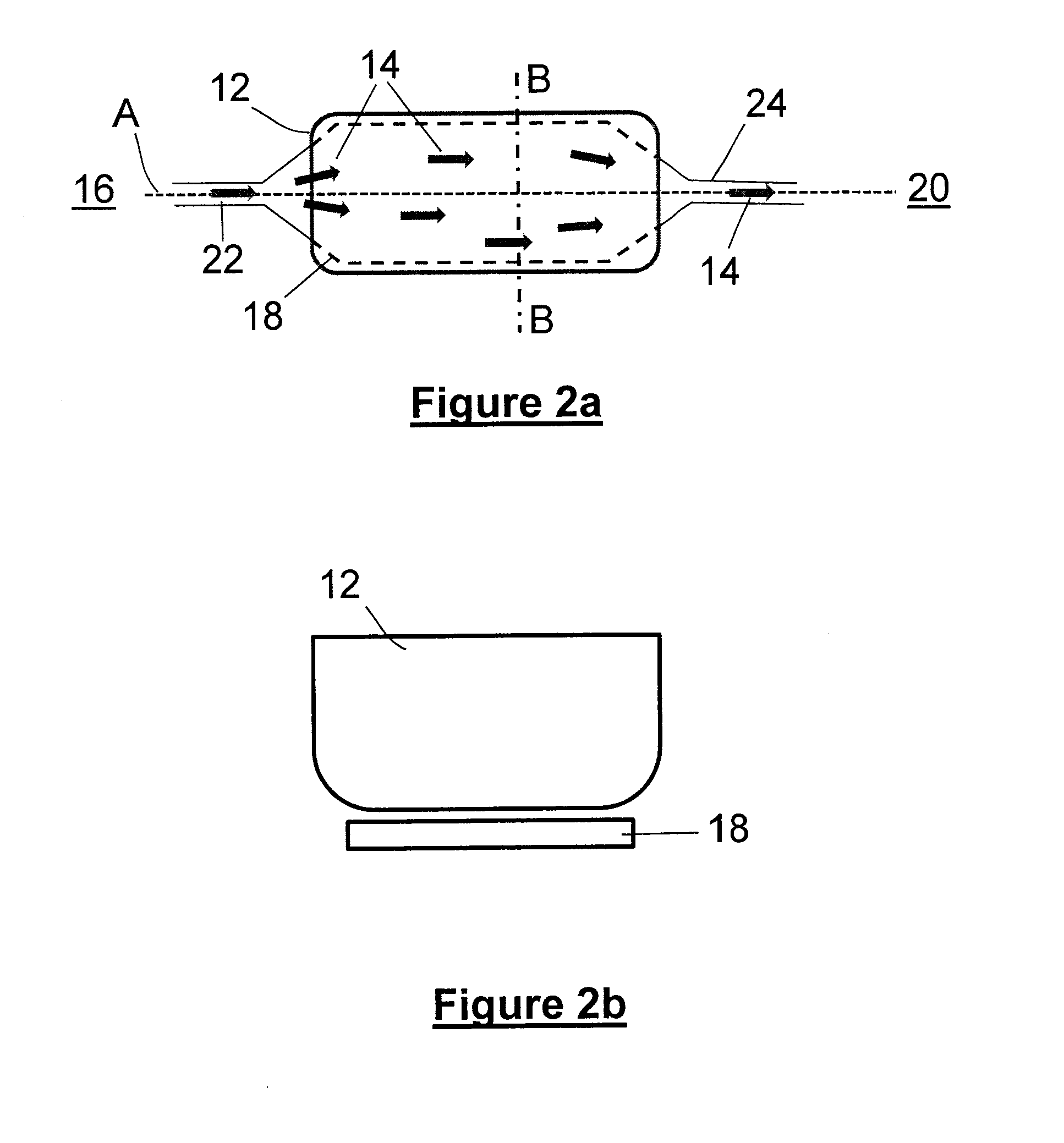
[0019]FIGS. 1, 2a and 2b illustrate highly schematically the invention. FIG. 1 shows an aircraft comprising a fuselage fuel tank 12. FIG. 2a shows the fuel tank in plan view with the axis A of the fuselage also shown. FIG. 2b shows a sectional view of fuselage fuel tank 12 taken about the cross-section B-B shown in FIG. 2a. Fuel in the fuselage fuel tank 12 is cooled by means of an airflow 14 resulting from cold air being drawn from the exterior of the aircraft. The air flows from an air inlet, shown schematically in FIG. 2a by reference numeral 16, to a cooling region 18, located to the exterior of the fuel tank 12. The air inlet 16 may be provided on the fuselage, but may in other embodiments of the invention be provided at other locations on the aircraft 10. The cooling region 18 is in thermal communication with the fuel tank 12 thus allowing the airflow to cool the fuel in the fuel tank 12. Cooling the fuel in this way reduces the fuel flammability in the fuselage fuel tank 12. ...
second embodiment
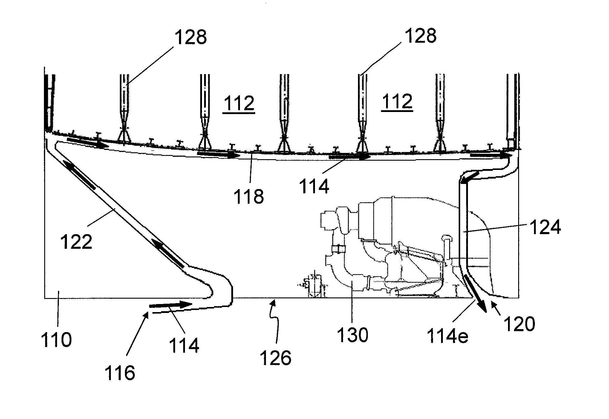
[0021]FIGS. 3 and 4 illustrate the invention. FIG. 3 shows an aircraft fuselage 110 comprising a fuselage fuel tank 112. FIG. 4 shows a sectional view of fuselage fuel tank 112 taken about a vertical plane parallel with the longitudinal axis of the fuselage. FIG. 4 shows the external surface 126 of the underneath of the fuselage 110 and the frame members 128 that make up the supporting structure (or frame) of the fuselage 110. A ram air intake 116, in the form of a NACA duct (illustrated schematically in FIG. 4), is provided on an external surface 126 of the fuselage 110. An air supply passage 122 extends from the ram air intake 116 to a cooling region, in the form of a cavity 118 immediately adjacent to and beneath the fuel tank 112. The wall (fuel tank wall) dividing the cavity 118 from the fuel tank 112 is shared. As a result, the cavity 118 is in thermal communication with the fuel tank 112. The cavity 118 leads to a downstream passageway 124, in the form of an air exhaust passa...
PUM
 Abstract
Description
Claims
Application Information