
Surface mount motor

a surface mount and motor technology, applied in the field of motors, can solve the problem that the bottom portion of the holder cannot be mounted, and achieve the effect of reducing the differences between the raising amount and the raising amount of the holder, easy setting to a uniform value, and easy adjustment of the raising amoun

Active Publication Date: 2011-12-01
COPAL CO LTD
View PDF15 Cites 16 Cited by
  • Summary
  • Abstract
  • Description
  • Claims
  • Application Information

AI Technical Summary

Benefits of technology

[0006]An object of the present invention is to provide a surface mount motor with which the heights of a mounting surface of a holder and mounting surfaces of terminals in a motor body can be easily adjusted.
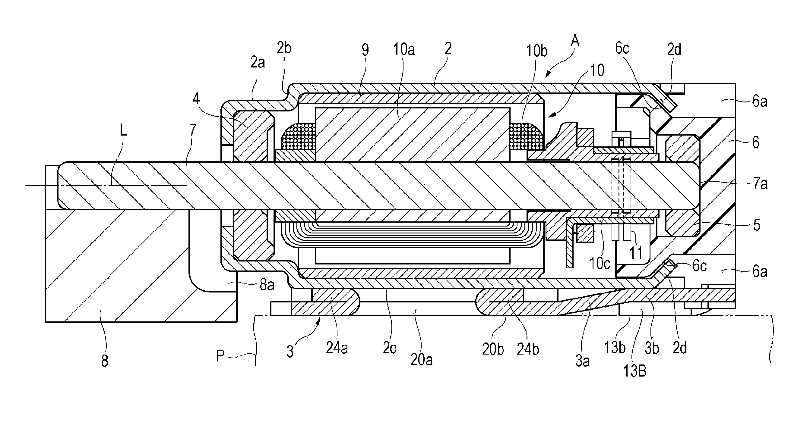
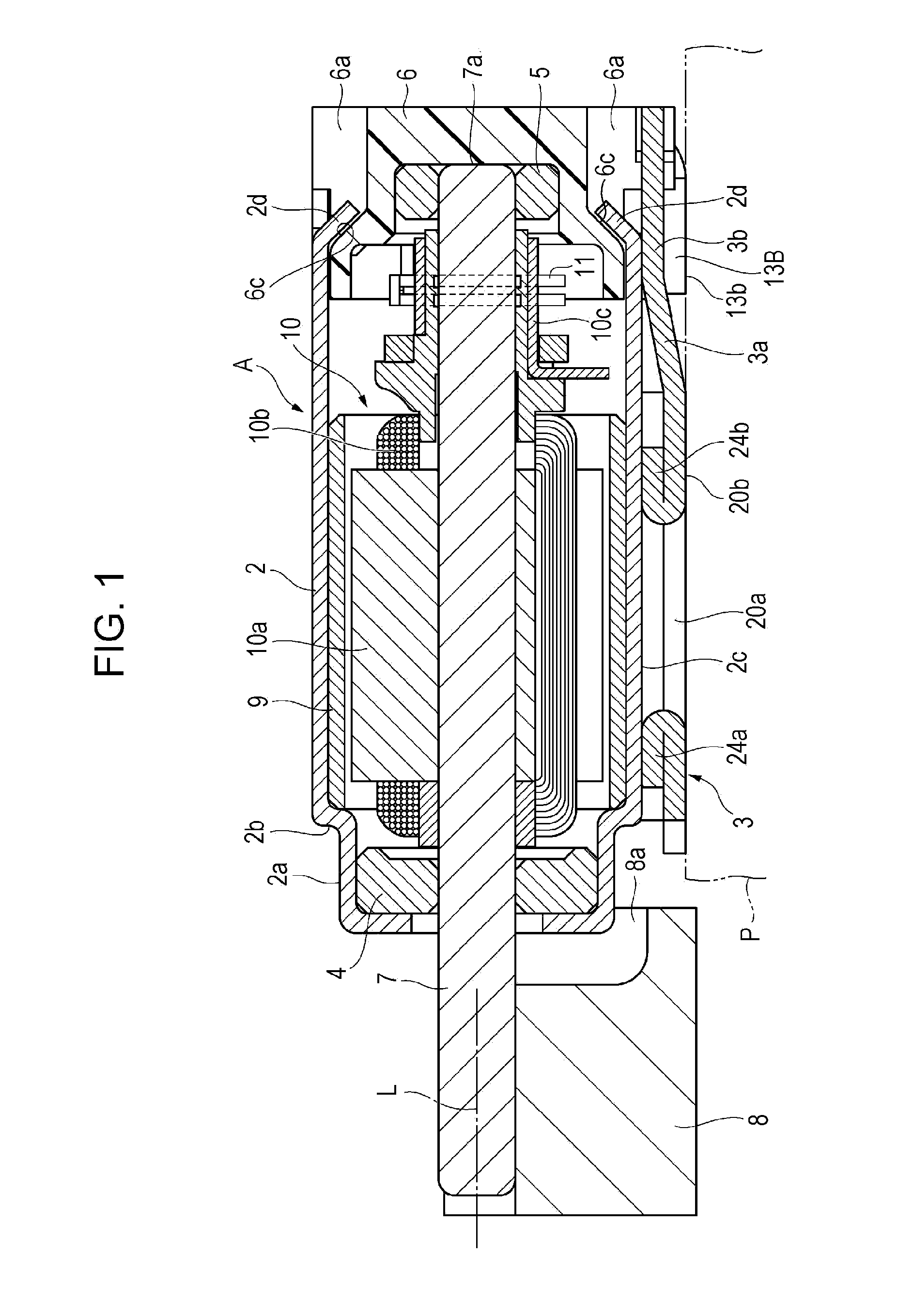
[0008]The holder for the surface mount motor includes the bottom-raising piece formed so as to extend integrally from the bottom portion, the bottom-raising piece being bent at the predetermined bending angle with respect to the bottom portion. When the holder is attached to the motor body, there is a risk that a mounting surface of the bottom portion of the holder will not be in the same plane as a mounting surface of the terminal. In such a case, a fine adjustment may be performed simply by slightly raising or lowering the bottom-raising piece. Thus, an adjustment between the heights of the mounting surface of the bottom portion of the holder and the mounting surface of the terminal can be easily performed. A gap (raising amount) between the bottom portion of the holder and the motor casing can be easily changed simply by changing the bending angle of the bottom-raising piece. In particular, depending on the specification, a weight must be provided on a shaft in the motor body such that the weight does not interfere with the circuit board when the weight rotates. In such a case, it is necessary to increase the raising amount of the motor casing. Also in this case, the raising amount can be easily increased by changing the bending angle of the bottom-raising piece. The bottom-raising piece can be easily formed by a bending process.
[0012]In such a case, the raising amount of the motor casing can be set to twice the thickness of the bottom portion. Thus, differences between the raising amounts of holders can be reduced and the raising amounts can be easily set to a uniform value. In addition, the cream solder in a molten state enters the opening, so that the holder is not easily detached from the circuit board.
[0013]According to the present invention, an adjustment between the heights of the mounting surface of the holder and the mounting surface of the terminal on the motor body can be easily performed.

Problems solved by technology

When the holder is attached to the motor body, there is a risk that a mounting surface of the bottom portion of the holder will not be in the same plane as a mounting surface of the terminal.

Method used


Image

  • Surface mount motor
  • Surface mount motor
  • Surface mount motor

Examples


Embodiment Construction

[0030]A surface mount motor according to an embodiment of the present invention will be described with reference to the drawings. In the following description, the side at which a weight is provided is defined as the “front side”.

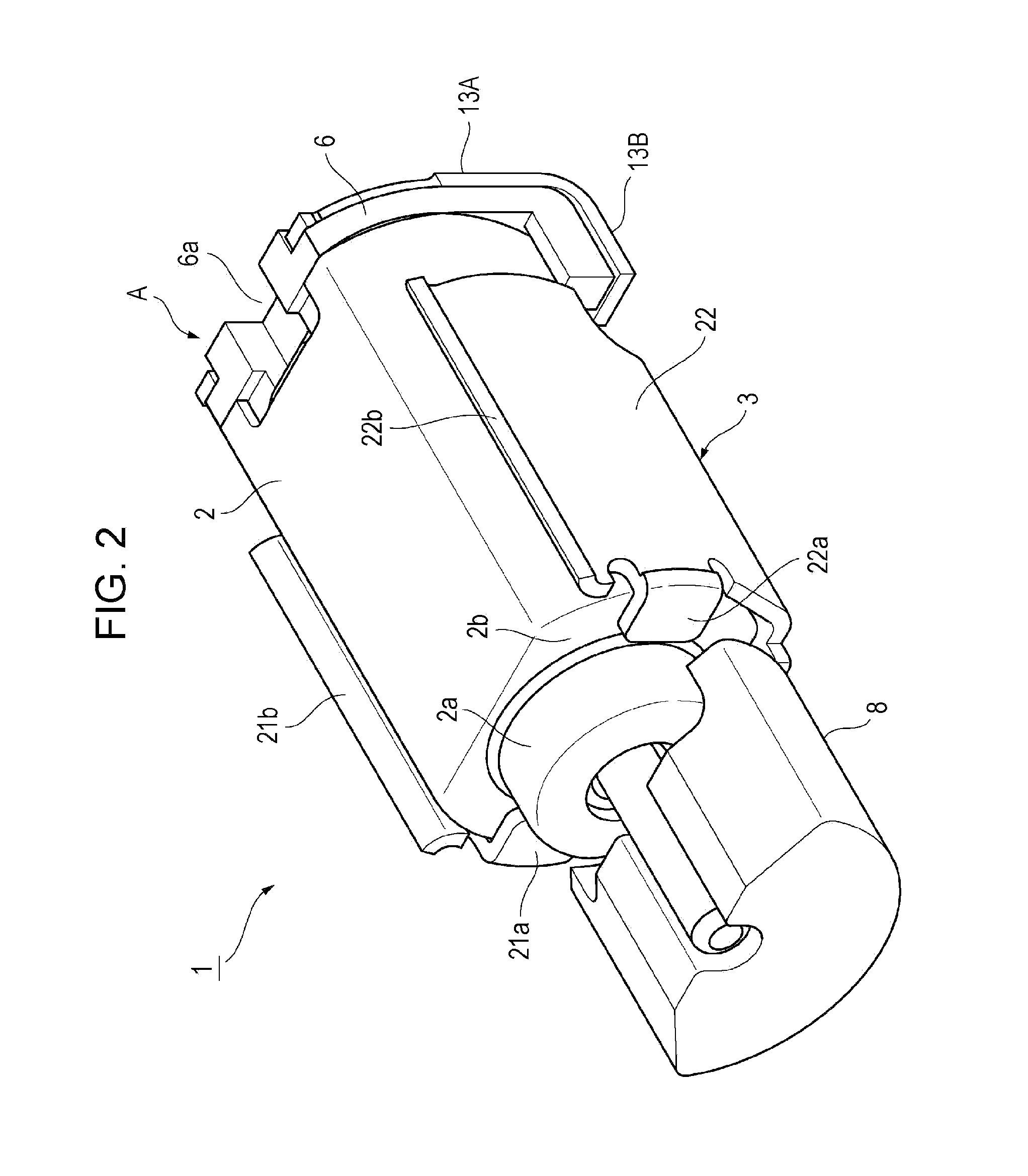
[0031]Referring to FIGS. 1 to 4, a surface mount motor 1 is a small vibration motor that is surface-mounted on a printed wiring board (circuit board) P by reflow soldering. The motor 1 includes a motor body A and a metal holder 3. The motor body A includes a motor casing 2 that has a tubular shape with a diameter of about 4 mm and a length of about 10 mm. The metal holder 3 is attached to the motor casing 2 of the motor body A such that the motor body A can be mounted on the printed wiring board P.

[0032]The motor casing 2 is made of a metal, and has a cylindrical shape or an oval shape in cross section. The motor casing 2 is open at the rear end thereof, and a bracket 6 made of resin is attached to the rear end of the motor casing 2. The motor casing 2 is p...


PUM


Abstract

A holder of a surface mount motor includes a bottom-raising piece formed so as to extend integrally from the bottom portion and bent at a predetermined bending angle with respect to the bottom portion. When the holder is attached to a motor body, there is a risk that a mounting surface of the bottom portion of the holder will not be in the same plane as a mounting surface of a terminal. In such a case, a fine adjustment may be performed simply by slightly raising or lowering the bottom-raising piece. Thus, an adjustment between the heights of the mounting surface of the bottom portion of the holder and the mounting surface of the terminal can be easily performed. A gap between the bottom portion of the holder and the motor casing can be easily changed simply by changing the bending angle of the bottom-raising piece.

Description

BACKGROUND OF THE INVENTION[0001]1. Field of the Invention[0002]The present invention relates to a motor suitable for surface mounting on a circuit board.[0003]2. Description of the Related Art[0004]Japanese Unexamined Patent Application Publication No. 11-234943 discloses an example of a technique in this field. A surface mount motor described in this publication includes a motor body and a metal holder frame fixed to the motor body. The motor body is a brush motor and has a substantially columnar drum portion (motor casing). The rear end of the substantially columnar drum portion is closed by an end bracket made of resin. Terminal pieces (terminals) that are mounted on a circuit board and brush terminal pieces that slide with respect to a commutator are fixed to the end bracket. The metal holder frame includes a holder body that is attached to the drum portion of the motor body. The holder body includes a rectangular bottom plate portion which contacts the circuit board and a pair...

Claims


Application Information

Patent Timeline
Patent Type & Authority Applications(United States)
IPC IPC(8): H02K5/26
CPCH02K5/04H02K7/061H02K5/225H02K11/00
Inventor HARA, KENTARO
Owner COPAL CO LTD
Learn More