Smart Battery Charging System For Electrical Generator

a charging system and battery technology, applied in the field of smart battery charging system for electrical generators, can solve the problems of reducing the maximum charge of the battery, affecting the operation of the battery, generating heat and gas, etc., and achieve the effect of avoiding overcharging the battery

Inactive Publication Date: 2011-12-01
GENERAC POWER SYSTEMS
View PDF9 Cites 22 Cited by
  • Summary
  • Abstract
  • Description
  • Claims
  • Application Information

AI Technical Summary

Benefits of technology

The present invention is directed to a battery charging system for charging the battery of an electrical generator and doing so in a manner that extends battery life and maintenance intervals by only applying the amount of charge necessary to maintain a full charge during a charging interval for the battery. Depending upon the charge of the battery, the charge applied to bring the battery to a full charge may be applied in a boost (fast) charge or in a trickle charge.
It is therefore an object of the invention to provide a battery charging system for use with an electrical generator that provides dynamic charging of the battery to avoid overcharging of the battery.

Problems solved by technology

Over time however the maximum charge of the battery will decline until ultimately the battery lacks the charge to energize the starter motor and the electrical generator will be unable to supply backup electrical power.
As a result, it is possible for a fully charged battery to still be exposed to a charging current, which can ultimately damage the battery.
The result is the generation of heat and gases both of which are bad for the battery.
For example, electronics of the electrical generator will deplete the battery, which may therefore require continuous cycling of the connection of the battery to the alternator.
On the other hand, if a trickle or slow charge is used, there may not be enough current to fully charge the battery.

Method used


Image

  • Smart Battery Charging System For Electrical Generator
  • Smart Battery Charging System For Electrical Generator
  • Smart Battery Charging System For Electrical Generator

Examples


Embodiment Construction

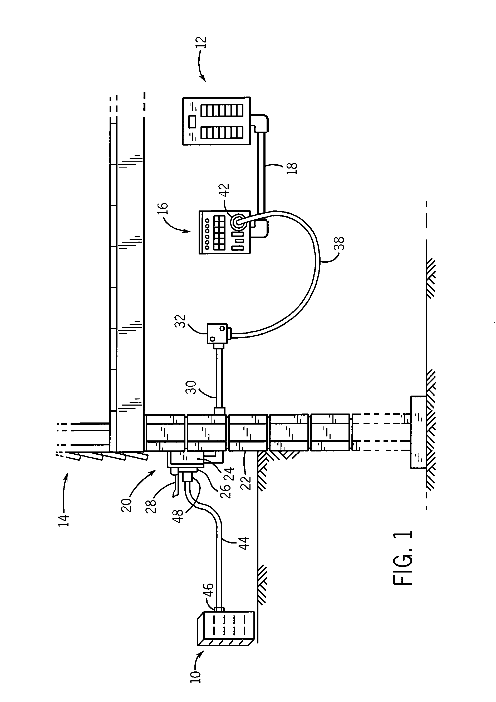
FIG. 1 shows a power inlet arrangement for interconnecting a generator 10 with a main electrical panel or load center 12 located in the interior of a building 14. In the power inlet arrangement of FIG. 1, a power transfer panel 16 is mounted adjacent main panel 12, and is interconnected therewith via a series of wires enclosed by a conduit 18 extending between main panel 12 and transfer panel 16.

A power inlet box 20 is mounted to the wall of building 14, shown at 22. Power inlet box 20 includes an external housing including a series of walls such as 24, and a receptacle 26 mounted to a front wall of the housing. A cover 28 is mounted to the front wall of the housing via a hinge structure, and is movable between an open position as shown in FIG. 1 and a closed position in which cover 28 encloses receptacle 26 when not in use. A conduit 30 extends between inlet box 20 and a junction box 32, and a flexible cord 38 is attached at one end to junction box 32. At its opposite end, flexible...


PUM

PropertyMeasurementUnit
temperatureaaaaaaaaaa

Abstract

An electrical generator has an engine that provides a mechanical output that is converted to electrical current by an alternator. The engine is started by a battery-powered motor starter. The battery is charged during running of the electrical generator by a portion of the electrical current output by the alternator. The battery is charged according to a charging profile based on the temperature of the battery at start up of the electrical generator.

Description

BACKGROUND AND SUMMARY OF THE INVENTIONElectrical generators are used in a wide variety of applications. Typically, an electrical generator operates in a stand-by mode wherein the electrical power provided by a utility is monitored such that if the commercial electrical power from the utility fails or is otherwise interrupted for a certain period of time, the engine of the electrical generator is started, either automatically or manually by a customer, causing the generator to supply emergency or backup electrical power. More particularly, the engine drives an alternator to provide electrical current to power selected electrical loads that are connected to the electrical generator, which is typically through a dedicated electrical panel, i.e., transfer panel.When the electrical power generated by the alternator reaches a predetermined voltage and frequency desired by the customer, a transfer switch transfers the load imposed by the customer from the commercial power lines to the ele...

Claims


Application Information

Patent Timeline
Patent Type & Authority Applications(United States)
IPC IPC(8): H02J7/04H02J7/00H01M50/569
CPCH01M10/4257H01M10/44H01M10/443H02J7/1415H01M10/48H01M10/486H01M10/46Y02E60/10H01M50/569
Inventor ILES, ROBERTDIETRICH, ALANWILCOX, STEVENWISCHSTADT, GREGTHIMMESCH, DAVID
Owner GENERAC POWER SYSTEMS
Why Eureka
Try Eureka