Method for reducing magnetic resonance temperature measurement errors

a technology of magnetic resonance and temperature measurement, applied in the field of high-intensity focused ultrasound (hifu) field for magnetic resonance imaging (mri) monitoring, can solve the problems of temperature measurement error, limited movement range of ultrasonic transducers, and additional phase difference, so as to speed up the whole treatment process, reduce the complexity level of temperature measurement, and reduce the effect of temperature measurement errors

Inactive Publication Date: 2011-12-01
SIEMENS HEALTHCARE GMBH
View PDF20 Cites 3 Cited by
  • Summary
  • Abstract
  • Description
  • Claims
  • Application Information

AI Technical Summary

Benefits of technology

[0019]From the above solution we can see that the present invention compensates for the temperature measurement according to the magnetic field caused by the ultrasonic transducer, and the temperature errors caused by position changes of the ultrasonic transducer can be significantly reduced. Compared with the existing single reference image method, the method of the invention does not required frequent collection of reference images at different positions of the ultrasonic transducer, which reduces the com

Problems solved by technology

However, in the actual heating process, the position of the ultrasonic transducer (i.e. treating head) may change after collecting one reference image, and the magnetic susceptibility changes caused by the movement of the ultrasonic transducer will result in static magnetic field changes in the focus area of the ultrasonic transducer, causing the heating image subtracted from the reference image to generate an additional phase difference, leading to temperature measurement errors.
This method limits the movement range of the ultrasonic transducer after collecting the reference image, thereby limiting the temperature errors to an acceptable range.
However, the space usage range of one reference image is very small, and the ultrasonic transducer wil

Method used


Image

  • Method for reducing magnetic resonance temperature measurement errors
  • Method for reducing magnetic resonance temperature measurement errors
  • Method for reducing magnetic resonance temperature measurement errors

Examples


Embodiment Construction

[0022]In order to further explain the purpose, technical solution and advantages of the present invention, the following will further describe the present invention by using embodiments.

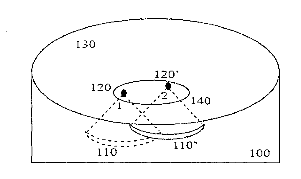
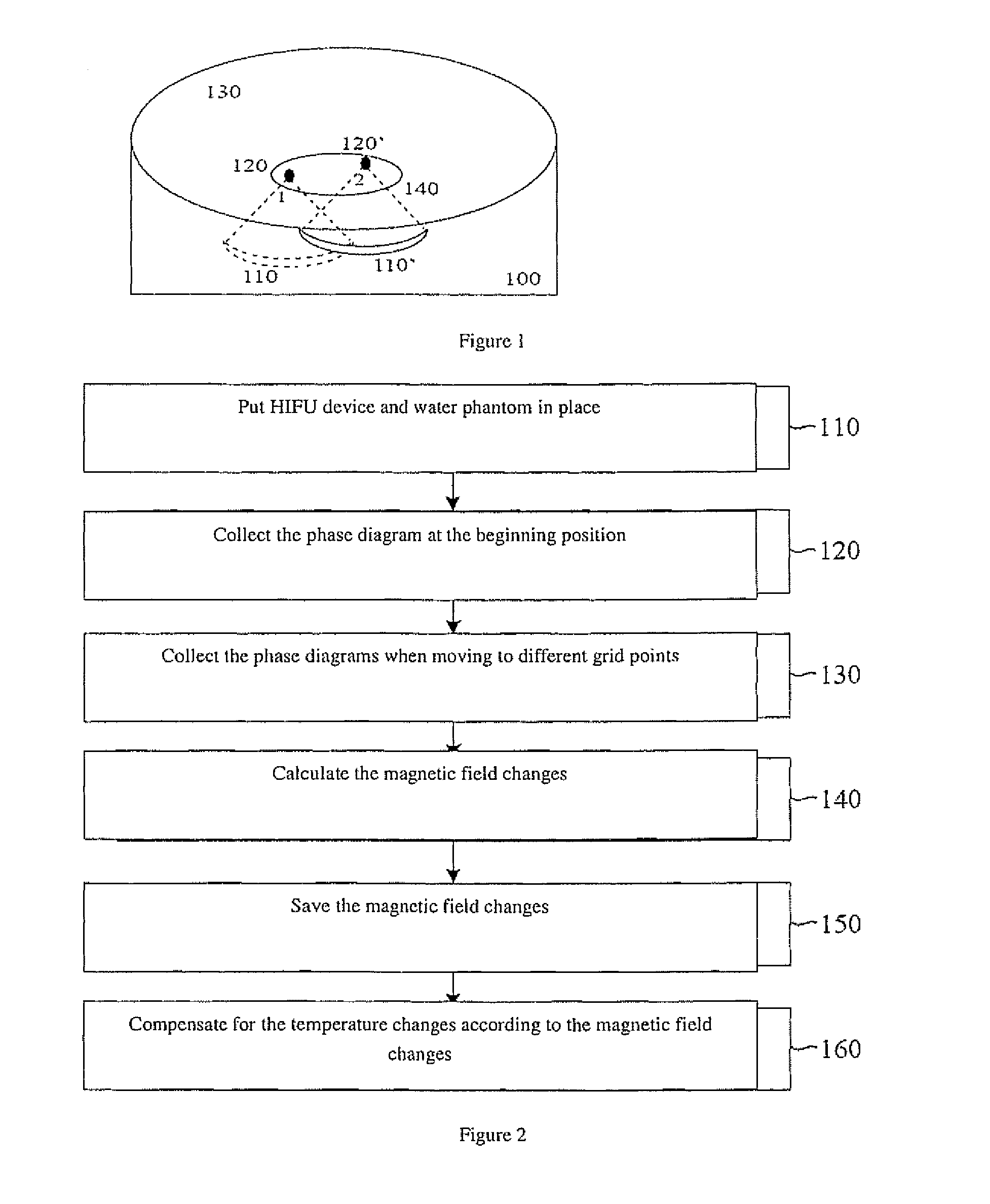
[0023]In FIG. 1, 100 is the water tank, 110 and 110′ are the ultrasonic transducer before and after moving respectively, 120 and 120′ are the corresponding focuses of 110 and 110′ respectively, 130 is the patient's body, and 140 is the heating area of the HIFU device, such as a tumor.

[0024]The MR phase diagram is measured by using the gradient echo sequence, and the proton resonance frequency will change as the local temperature changes in the measured tissue, resulting in changes in the PRF, and the PRF changes can be reflected in the MR phase diagram. Therefore, the temperature change can be represented as:

ΔT=Δϕγ·B0·α·TE(1)

wherein ΔT is the temperature change, γ is the gyromagnetic ratio of the hydrogen atomic nucleus (42.58×10⁶ Hz / T for proton), B0 is the static magnetic field intensity, TE is the...


PUM


Abstract

A method for reducing magnetic resonance temperature measurement errors, which is used for the high-intensity focused ultrasound device for monitoring magnetic resonance imaging includes obtaining a magnetic resonance phase diagram as a reference image before the high-intensity focused ultrasound device heats the heating area; obtaining another magnetic resonance phase diagram as a heating image during or after the heating process of the high intensity focused ultrasound device; calculating the temperature changes in the heating area according to said heating image and reference image. The method further includes measuring the magnetic field changes caused by the position changes of the ultrasonic transducer of said high-intensity focused ultrasound device, and then compensating for the temperature changes according to said magnetic field changes. The present invention can significantly reduce the temperature errors caused by the position changes of the ultrasonic transducer.

Description

BACKGROUND OF THE INVENTION[0001]1. Field of the Invention[0002]The present invention relates to the high-intensity focused ultrasound (HIFU) field for magnetic resonance imaging (MRI) monitoring, and more particularly to a method for reducing temperature measurement errors of the HIFU device for MRI monitoring.[0003]2. Description of the Prior Art[0004]The Magnetic Resonance (MR) Proton Resonance Frequency (PRF) temperature measurement method can be used to monitor the temperature changes of the HIFU heating part in the HIFU device for MRI monitoring, and its principle is to use the phenomenon that the resonance frequency of protons in water will drift as the temperature changes. The PRF temperature measurement method requires the generation of one benchmark image (MR phase diagram), also known as reference image, before the heating process starts. This reference image provides reference phase information, used to perform subtraction from the phase diagram (also known as heating im...

Claims


Application Information

Patent Timeline
IPC IPC(8): G01R33/44
CPCA61B2017/00084A61B2019/5236G01R33/4814G01R33/4804A61N7/02A61B2090/374
Inventor NI, CHENGZHOU, XIAO DONG
Owner SIEMENS HEALTHCARE GMBH
Why Eureka
Try Eureka