Projection display system and attaching device

a projection display and projection display technology, applied in the field of projection display devices and attaching devices, can solve the problems of inability to realize position detection, increase the cost of parts, and inconvenient installation,

Inactive Publication Date: 2011-12-01
COLUMBIA PEAK VENTURES LLC
View PDF7 Cites 21 Cited by
  • Summary
  • Abstract
  • Description
  • Claims
  • Application Information

AI Technical Summary

Benefits of technology

[0008]An advantage of some aspects of the invention is to provide an attaching device and a projec...

Problems solved by technology

Therefore, it is difficult to realize position detection by using the above-described resistive touch panel or capacitive touch panel in the projection display device.
However, with this method, there is a possibili...

Method used


Image

  • Projection display system and attaching device
  • Projection display system and attaching device
  • Projection display system and attaching device

Examples


Embodiment Construction

[0060]Hereinafter, a preferred embodiment of the invention will be described in detail. It should be understood that the embodiment described below is not meant to limit unduly the scope of the invention claimed in the appended claims in any way, and all the configurations described in the embodiment are not always necessary for means for solving the problems.

1. Configuration of Attaching Device

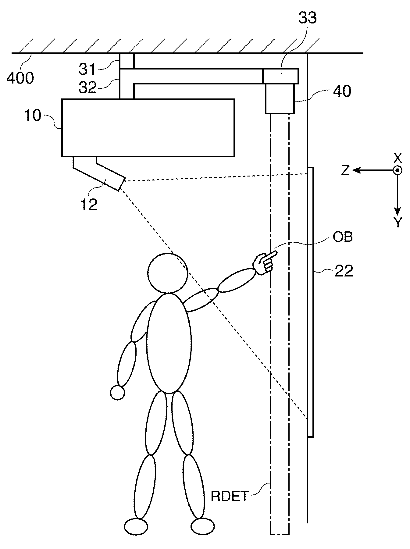
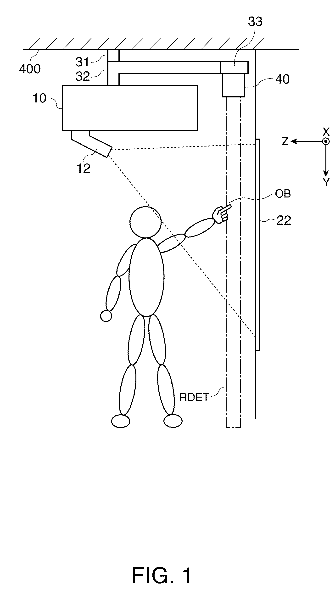
[0061]In FIG. 1, a configuration example of a projection display device including an attaching device of this embodiment and an image projection device 10 attached to the attaching device is shown. FIG. 1 shows an example in which the attaching device (in a more limited sense, ceiling-hung fittings) of this embodiment is used as an attaching device of an image projection device 10 called a liquid crystal projector or a digital micromirror device. In addition, the attaching device and the image projection device 10 attached to the attaching device form a projection display device. Incidentally...


PUM


Abstract

A projection display system includes: an image projection device projecting an image on a projection surface; an optical detecting device; and an attaching device, wherein the optical detecting device includes an irradiating section emitting an irradiation light toward a detection region which is set along the projection surface, a light receiving section receiving a reflected light generated as a result of the irradiation light being reflected from the object, and a detecting section detecting position information of the object based on the result of the light received by the light receiving section, and the attaching device includes a first attaching section attached to a support supporting the attaching device, a second attaching section attached to the image projection device, and a third attaching section attached to the optical detecting device.

Description

BACKGROUND[0001]1. Technical Field[0002]The present invention relates to attaching devices and projection display devices etc.[0003]2. Related Art[0004]In recent years, in electronic equipment such as a cellular telephone, a personal computer, a car navigation device, a ticket-vending machine, and a bank terminal, a display device having a position detecting function, the display device provided with a display section having a front face on which a touch panel is placed, has been used. This display device allows the user to point at an icon or the like in a display image or input information while referring to an image displayed on the display section. As a position detecting method using such a touch panel, a method using a resistive touch panel or a capacitive touch panel, for example, has been known.[0005]On the other hand, the display area of a projection display device using an image projection device (a projector) is wider than that of the display device of the cellular teleph...

Claims


Application Information

Patent Timeline
IPC IPC(8): G06F3/042G03B21/16G03B21/14
CPCF16M13/02G06F3/0425G06F3/0428G06F3/0418F16M13/027G03B21/145G03B21/16G03B21/206
Inventor KIYOSE, KANECHIKAONISHI, YASUNORI
Owner COLUMBIA PEAK VENTURES LLC
Why Eureka
Try Eureka