Light emitting device and illumination device

a technology of light emitting devices and illumination devices, which is applied in the direction of vehicle headlamps, transportation and packaging, lighting and heating apparatus, etc., can solve the problems of disadvantageous improvement of light extraction efficiency, and achieve the reduction of the size and weight of the light emitting device, the effect of reducing the size and weight of the laser light sour

Inactive Publication Date: 2011-12-01
SHARP KK
View PDF0 Cites 42 Cited by
  • Summary
  • Abstract
  • Description
  • Claims
  • Application Information

AI Technical Summary

Benefits of technology

[0027]Preferably, in the above-described light emitting device according to the first aspect, the fluorescent body is provided on a fourth laser light output surface of the reflective polarization filter. With this structure, it is possible to form the reflective polarization filter and the fluorescent body as one piece, and this helps reduce the size and weight of the light emitting device.
[0028]Preferably, the above-described light emitting device according to the first aspect further includes a reflecting mirror which reflects light from the fluorescent body in a predetermined direction and a light guide member which is arranged in the region through which the laser light outputted from the laser generator passes, the reflecting mirror includes an opening through which the laser light outputted from the laser generator passes, and the light guide member is fitted in the opening of the reflecting mirror. With this structure, it is possible to restrict increase in size of the opening, and thus to further restrict the light from the fluorescent body from returning to the laser generator side through the opening.
[0029]Preferably, in the light emitting device

Problems solved by technology

This makes it disadvantageously difficult to improve the l

Method used


Image

  • Light emitting device and illumination device
  • Light emitting device and illumination device
  • Light emitting device and illumination device

Examples


first embodiment

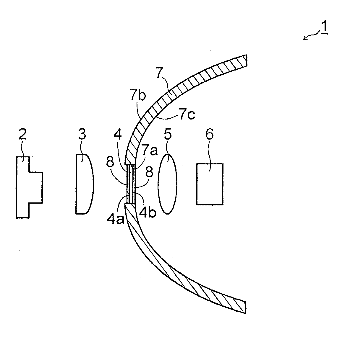
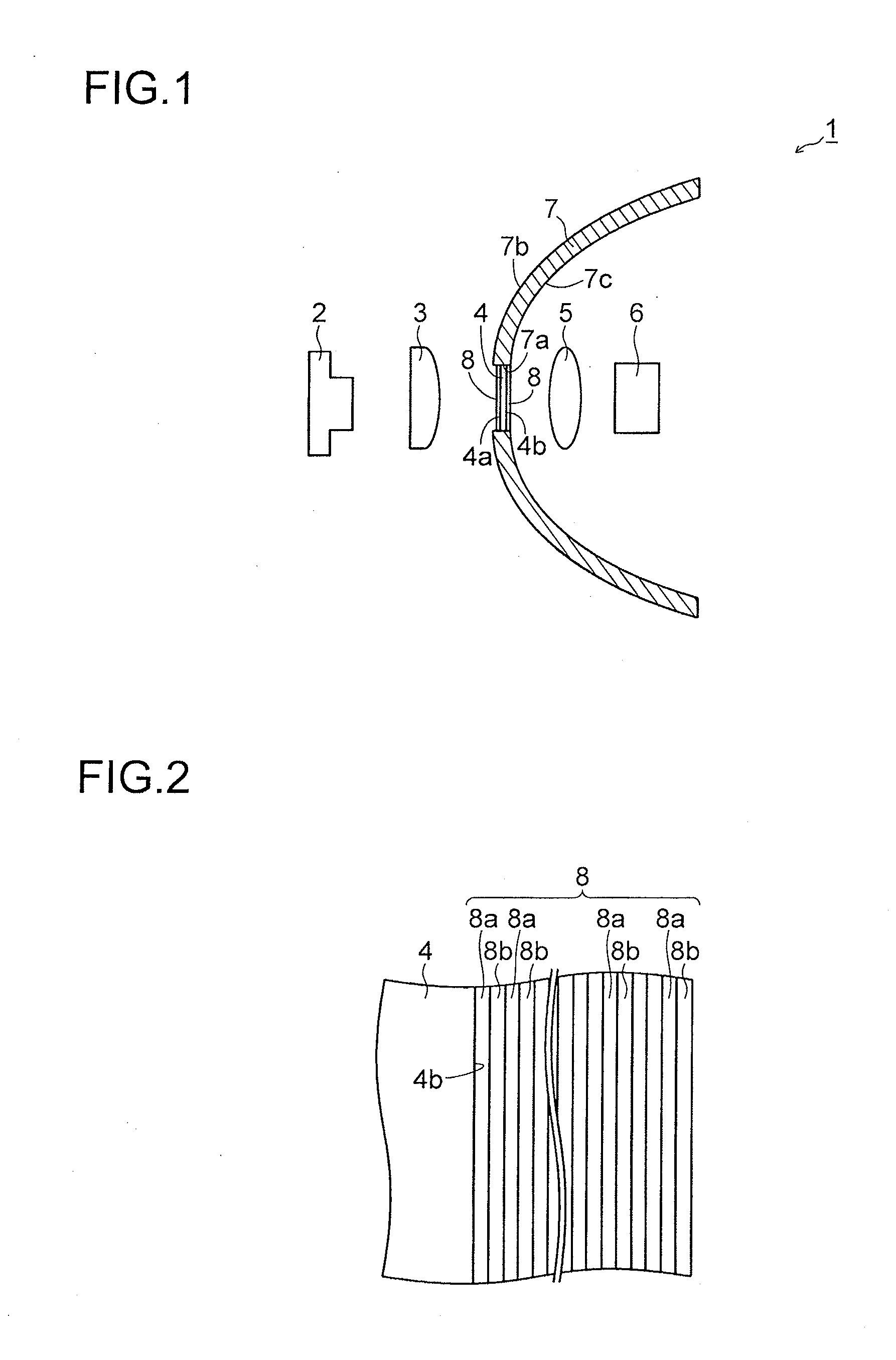
[0052]A description will be given of the structure of a light emitting device 1 of a first embodiment of the present invention with reference to FIGS. 1 and 2.

[0053]A light emitting device 1 according to the first embodiment of the present invention is usable as an illumination device such as a vehicle head lamp as well, and includes, as shown in FIG. 1, a semiconductor laser element 2, a collimator lens 3 which is arranged in front of the semiconductor laser element 2, a light transmitting member 4 which is arranged in front of the collimator lens 3, a lens 5 which is arranged in front of the light transmitting member 4, a fluorescent body 6 which is arranged in front of the lens 5, and a reflecting mirror 7. The semiconductor laser element 2, the collimator lens 3, the light transmitting member 4, the lens 5, and the fluorescent body 6 are arranged in line. Here, the semiconductor laser element 2 is an example of a “laser generator” of the present invention.

[0054]The semiconductor...

second embodiment

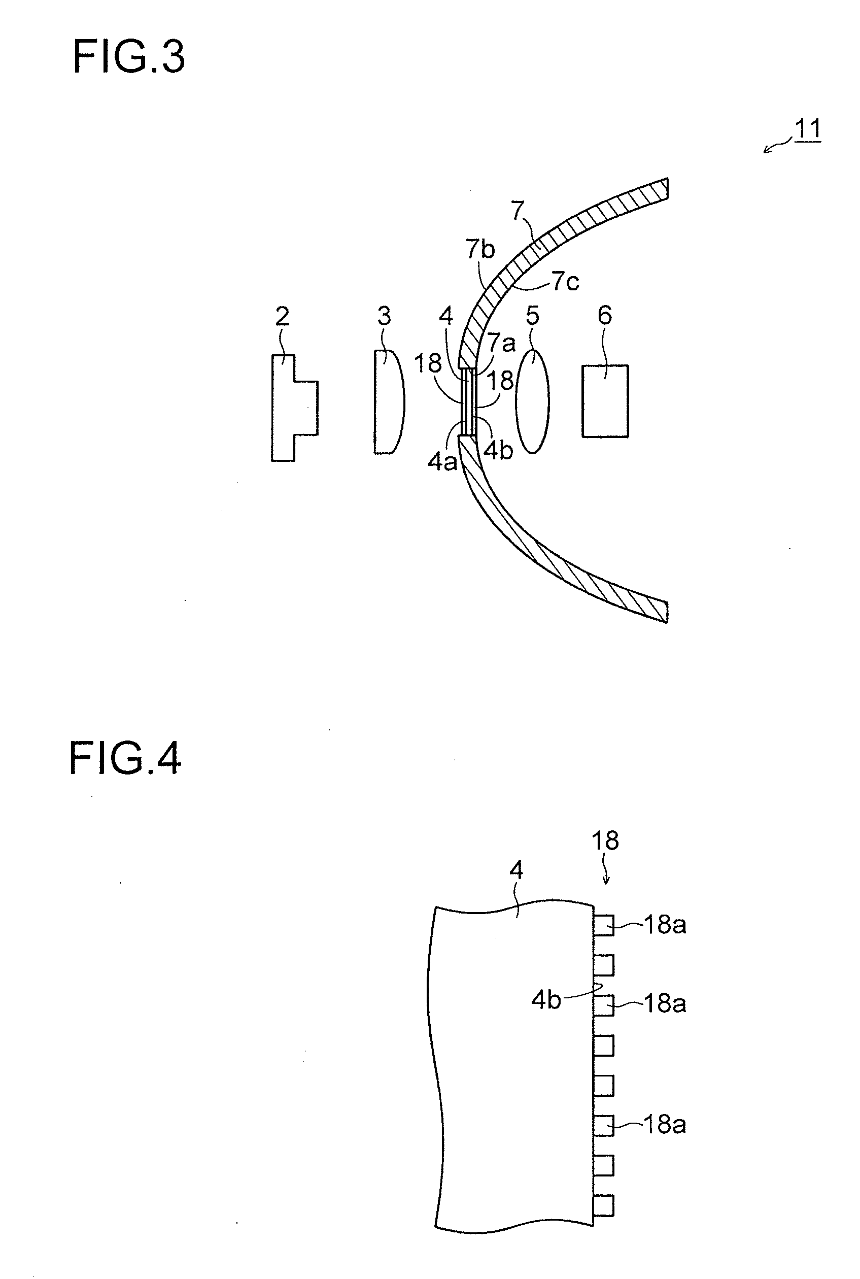
[0084]The following description of a second embodiment, which will be given with reference to FIGS. 3 and 4, will deal with a case in which a reflective polarization filter 18 is formed of a wire grid in contrast to the above-described first embodiment.

[0085]In a light emitting device 11 according to the second embodiment of the present invention, as shown in FIG. 3, the reflective polarization filter 18 is formed on each of a laser light input surface 4a and a laser light output surface 4b of a light transmitting member 4.

[0086]In the second embodiment, the light transmitting member 4 may be formed of a material other than an SiO2 substrate, such as an SiC substrate, as long as the material transmits light.

[0087]The reflective polarization filter 18 may be provided only on either one of the laser light input surface 4a and the laser light output surface 4b of the light transmitting member 4, in the same manner as the reflective polarization filter 8 in the above-described first emb...

third embodiment

[0099]The following description of a third embodiment, which will be given with reference to FIG. 5, will deal with a case in which a light transmitting member 24 and reflective polarization filters 28 are not fitted in an opening 27a of a reflecting mirror 27, in contrast to the above-described first and second embodiments.

[0100]In a light emitting device 21 according to the third embodiment of the present invention, as shown in FIG. 5, a light transmitting member 24 and the reflective polarization filters 28 are each formed to have an external size that is larger than the diameter of an opening 27a of a reflecting mirror 27. That is, the light transmitting member 24 and the reflective polarization filters 28 are formed to have an area larger than the opening 27a of the reflecting mirror 27.

[0101]And, one of the reflective polarization filters 28 is in contact with an external surface 27b of the reflecting mirror 27 to close the opening 27a from outside (a side opposite to a fluore...


PUM


Abstract

A light emitting device capable of improving light extraction efficiency is provided. The light emitting device includes: a laser generator which outputs linearly polarized laser light; a fluorescent body which is irradiated with the laser light from the laser generator; and a reflective polarization filter which is arranged in a region through which the laser light outputted from the laser generator passes. The reflective polarization filter is formed to transmit linearly polarized light of the laser light and reflect linearly polarized light having a polarization plane which is perpendicular to a polarization plane of the linearly polarized light of the laser light.

Description

[0001]This application is based on Japanese Patent Application No. 2010-120794 filed on May 26, 2010, the contents of which are hereby incorporated by reference.BACKGROUND OF THE INVENTION[0002]1. Field of the Invention[0003]The present invention relates to a light emitting device and an illumination device. In particular, the present invention relates to a light emitting device and an illumination device including a laser generator and a fluorescent body.[0004]2. Description of Related Art[0005]Conventionally, light emitting devices including a laser generator and a fluorescent body have been known. An example of such light emitting devices is disclosed in JP-A-2003-295319.[0006]FIG. 18 is a sectional view showing the structure of a light source device (a light emitting device) disclosed in the above-mentioned JP-A-2003-295319. The above-mentioned JP-A-2003-295319 discloses the light source device as shown in FIG. 18, which includes: an ultraviolet ray LD element (a laser generator...

Claims


Application Information

Patent Timeline
IPC IPC(8): F21V9/14
CPCF21S48/1127F21S48/1241F21S48/115F21S41/12F21S41/16F21S41/176F21S41/24
Inventor FUKAI, YASUOKAWANISHI, HIDENORI
Owner SHARP KK
Why Eureka
Try Eureka