Systems and methods for measurement of geometrical parameters of threaded joints

a technology of geometric parameters and measurement methods, applied in the direction of speed measurement using gyroscopic effects, gyroscopes/turn-sensitive devices, diagnostics, etc., can solve the problems of adding costly time to the threading process, precision and repeatability of measurement operations, and performing measurement operations on threaded products

Active Publication Date: 2011-12-01
TENARIS CONNECTIONS
View PDF3 Cites 13 Cited by
  • Summary
  • Abstract
  • Description
  • Claims
  • Application Information

AI Technical Summary

Benefits of technology

[0021]An object of the embodiments of the present disclosure is to provide a method for accurate, non-contact inspection of threaded objects. In certain embodiments, the method may be performed automatically. In further embodiments, the method may be suitable for threads of pipes employed in oil exploration, especially of pins and boxes.

Problems solved by technology

A difficulty encountered in performing measurement operations on threaded products is the precision and repeatability of the measurements.
However, U.S. Pat. No. 5,712,706 does not explicitly address explicitly the issue of piece misalignment.
Unfortunately, performing measurements at the threading machine has several disadvantages.
In one aspect, performing measurements at the threading machine adds costly time to the threading process by inhibiting inspection and manufacturing from being performed at the same time.
Instead, performing measurements at the threading machine entails placing delicate optics and precise mechanical components in a hostile environment (e.g., cutting oil and strong vibrations present).
Once the piece has been removed from the lathe, this alignment is very difficult to achieve manually.
Measurement errors introduced by a piece misalignment are not “noticed” according to U.S. Pat. No. 5,712,706, and in these cases produces an insufficiently precise measurement.
Furthermore, U.S. Pat. No. 5,712,706 does not address the measurement of thread parameters such as taper, run-in, run-out, black crest, length of complete thread.
In case where a coating is applied to the pipe threading (e.g., a dry lubricant), additional problems are encountered.
Another difficulty encountered in performing measurement operations on coated joints is an inability to ensure that the coating material is not damaged during the measurement procedure (e.g., due to handling of the pipes and / or to the use of contact type measuring devices).
While measuring systems have been proposed for measuring coatings in general and measurement of coating applied on tubular products, none of these measurement systems is adapted to measurement of dry coatings applied on threaded parts of tubular joints.
In one example, a measurement technique employing ultrasound is known, however, it cannot be applied to coatings as thin as those applied in threaded joints for the hydrocarbon industry, since the wavelength of ultrasound is much larger than the thicknesses to be measured.
Because of the complex geometry and generation of boundary effects, it is difficult to use this technique on threaded parts of joints.
It is not a technique generally applicable and, in complex cases, the results depend on the angle of incidence of X-rays.
Another drawback is the use of X-rays which are harmful to operators.

Method used


Image

  • Systems and methods for measurement of geometrical parameters of threaded joints
  • Systems and methods for measurement of geometrical parameters of threaded joints
  • Systems and methods for measurement of geometrical parameters of threaded joints

Examples


Embodiment Construction

[0044]The terms “approximately,”“about,” and “substantially” as used herein represent an amount close to the stated amount that still performs a desired function or achieves a desired result. For example, the terms “approximately,”“about,” and “substantially” may refer to an amount that is within less than 10% of, within less than 5% of, within less than 1% of, within less than 0.1% of, and within less than 0.01% of the stated amount.

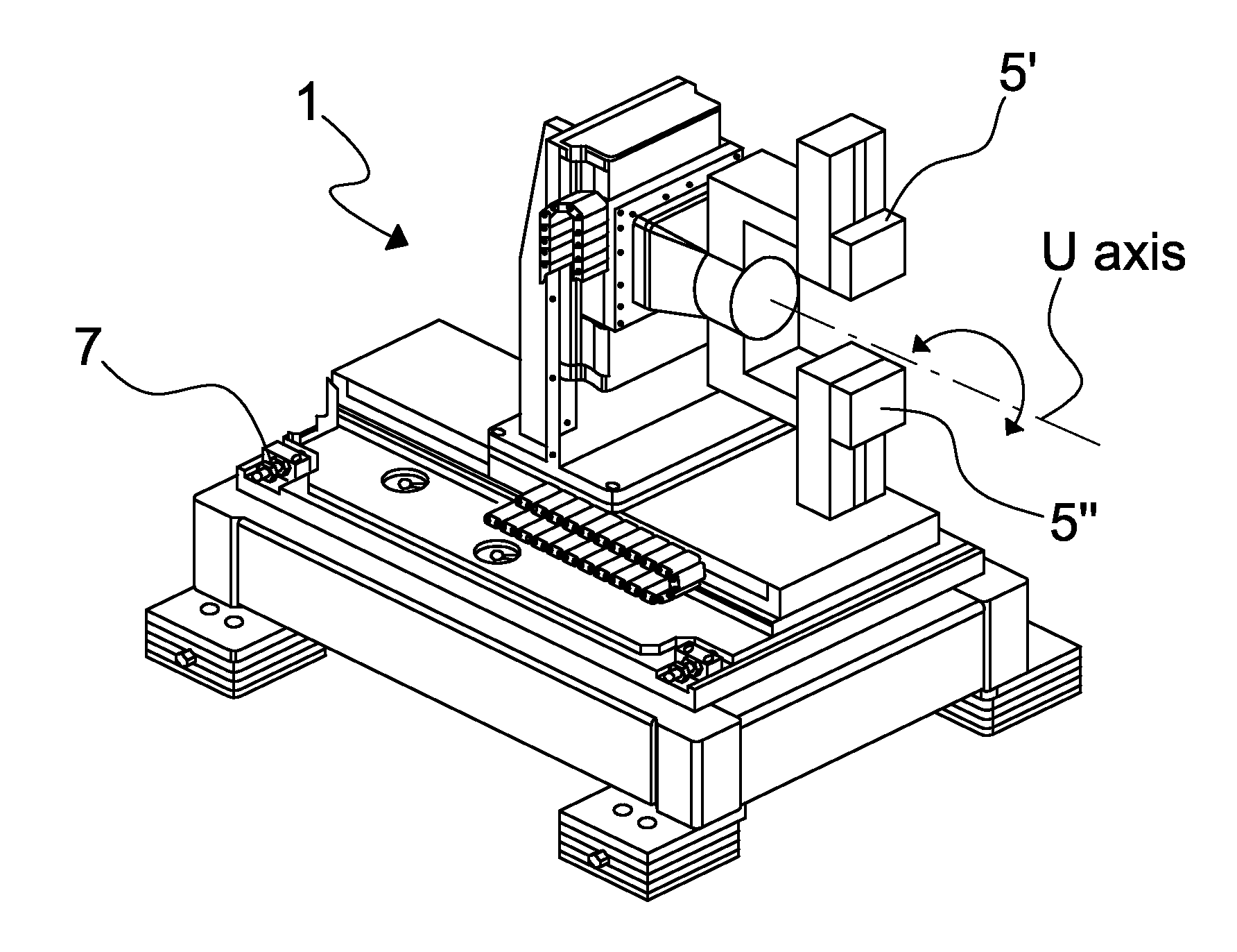
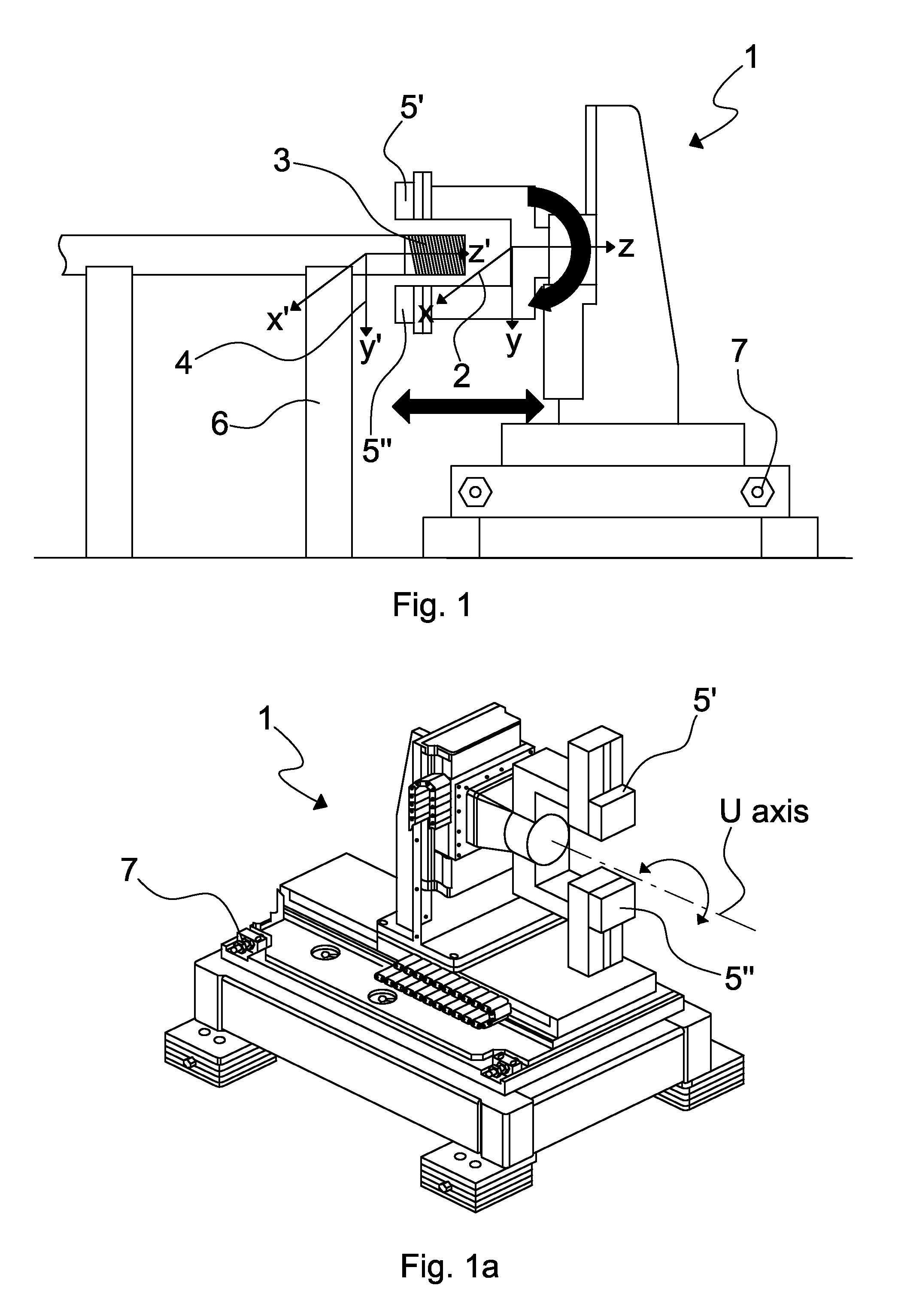
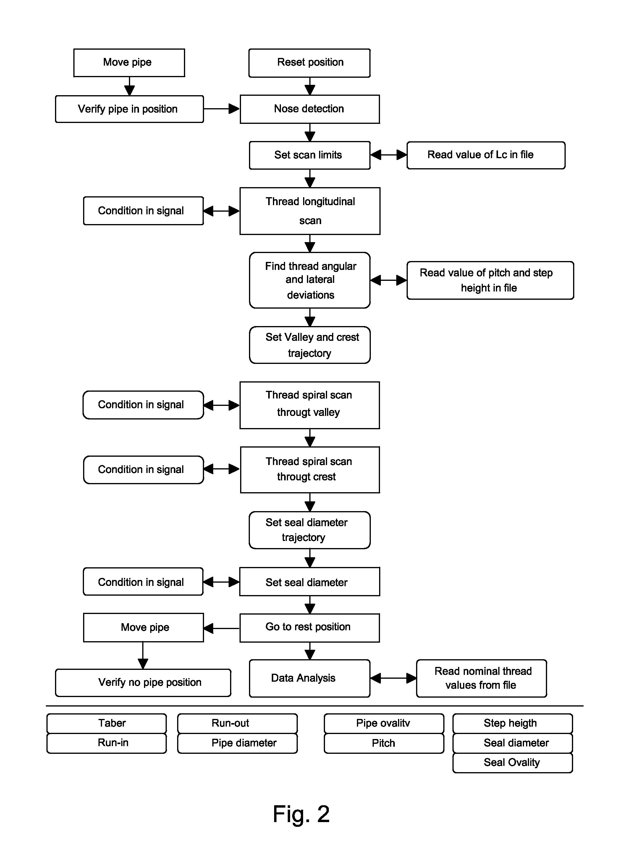
[0045]In the disclosed embodiments, reference is made to a pin of an oil or gas pipe. However it may be understood that embodiments of the disclosure may be applied to any other similar threaded objects, such as screws or similar objects. All these kinds of objects, at a certain stage of the measurement method, may be coated, using any type of coating technology. In certain embodiments, the coating may be a dry coating but, in alternative embodiments, other types of materials may be used as coatings, depending on the function to be achieved by the coati...


PUM


Abstract

Thread parameters for a threaded object are determined. Spatial reference systems (X, Y, Z) and (X′, Y′, Z′) are respectively identified for a position sensor and the threaded object. A transformation matrix describing a quadratic form representing the threaded object in (X, Y, Z) may be determined to relate the reference systems. For example, a sensor trajectory on the threaded object may be determined, along with measurement points on the threaded object. The measurement points may be selected so the matrix, evaluated on these values, has maximum rank. Position data at measurement points in the second reference system may be transformed into the first reference system, yielding first results. After coating the threaded object, position data at the measurement points may be acquired again and transformed into the first reference system, yielding second results. Comparisons between the first and second results may provide thickness of the coating and quality verification.

Description

CROSS-REFERENCE TO RELATED APPLICATIONS[0001]This application claims priority to European Patent Application No. 10164636.2, entitled “______”, filed Jun. 1, 2010, the entirety of which is hereby incorporated by reference and should be considered a part of this specification.BACKGROUND[0002]1. Field[0003]Embodiments of the present disclosure relate to measurement of geometrical parameters of threaded connections and for assessing the quality of a coating deposition process. The disclosed embodiments are especially suited for threaded pipes used in the hydrocarbon industry and for similar threaded objects.[0004]2. Description of the Related Art[0005]Oil and gas pipe connections may be prepared with dry coatings in order to avoid the use of dopes and attendant drawbacks. For example, documents EP 1554518, EP 1954953, and EP 2102542, the entirety of each of which are incorporated by reference, disclose threaded joints where all or part of the threading is covered with dry coating.[0006...

Claims


Application Information

Patent Timeline
Patent Type & Authority Applications(United States)
IPC IPC(8): G06K9/00G06F15/00
CPCG01B11/0616G06T11/005A61B6/027G01B11/2425
Inventor BONADEO, NICOLAS HERNANBERRA, SEBASTIANETCHEVERRY, JAVIER IGNACIO
Owner TENARIS CONNECTIONS
Why Eureka
Try Eureka