Method for manufacturing a complexly shaped composite material part

a composite material and complex shape technology, applied in weaving, machines/engines, mechanical equipment, etc., can solve the problems of increasing complexity and cost of fabricating parts, difficult or even impossible to make a fiber preform directly by three-dimensional weaving, and weak connections between the various portions of the preform, so as to preserve the deformation capacity of the fiber blank and increase the strength of the fiber blank

Active Publication Date: 2011-12-01
SAFRAN CERAMICS SA +1
View PDF6 Cites 61 Cited by
  • Summary
  • Abstract
  • Description
  • Claims
  • Application Information

AI Technical Summary

Benefits of technology

[0023]Advantageously, prior to impregnating with the consolidation composition, a fiber-matrix interphase layer is formed on the fibers of the woven fiber strip, the interphase layer being made of a material selected from pyrolytic carbon (SiC), boron nitride (BN), and boron-doped carbon (BC). The interphase layer preferably presents thickness of no more than 100 nanometers (nm) in order to preserve the deformation capacity of the fiber blank.
[0024]After impregnation with the consolidation composition and before cutting out the blanks, it is possible to perform pre-curing of the consolidation resin. Such pre-curing or partial curing may provide stiffness and thus additional strength of the fiber blank.
[0035]Thus, the method of the invention is remarkable in that the operations that precede shaping a fiber blank are performed on a continuous 3D woven strip that is easy to handle and that enables a plurality of blanks to be treated simultaneously. This provides a significant advantage in terms of fabricating a large number of similar parts.

Problems solved by technology

With parts that are complex in shape, it can be difficult or even impossible to make a fiber preform directly by three-dimensional (3D) weaving.
However the connections between the various portions of the preform may constitute points of weakness.
Those various operations require a great deal of manipulation, thereby increasing the complexity and the cost of fabricating parts.

Method used


Image

  • Method for manufacturing a complexly shaped composite material part
  • Method for manufacturing a complexly shaped composite material part
  • Method for manufacturing a complexly shaped composite material part

Examples


example 1

Fabricating Turbomachine Blades Out of CMC Material Having Inner and Outer Platforms Incorporated Therein

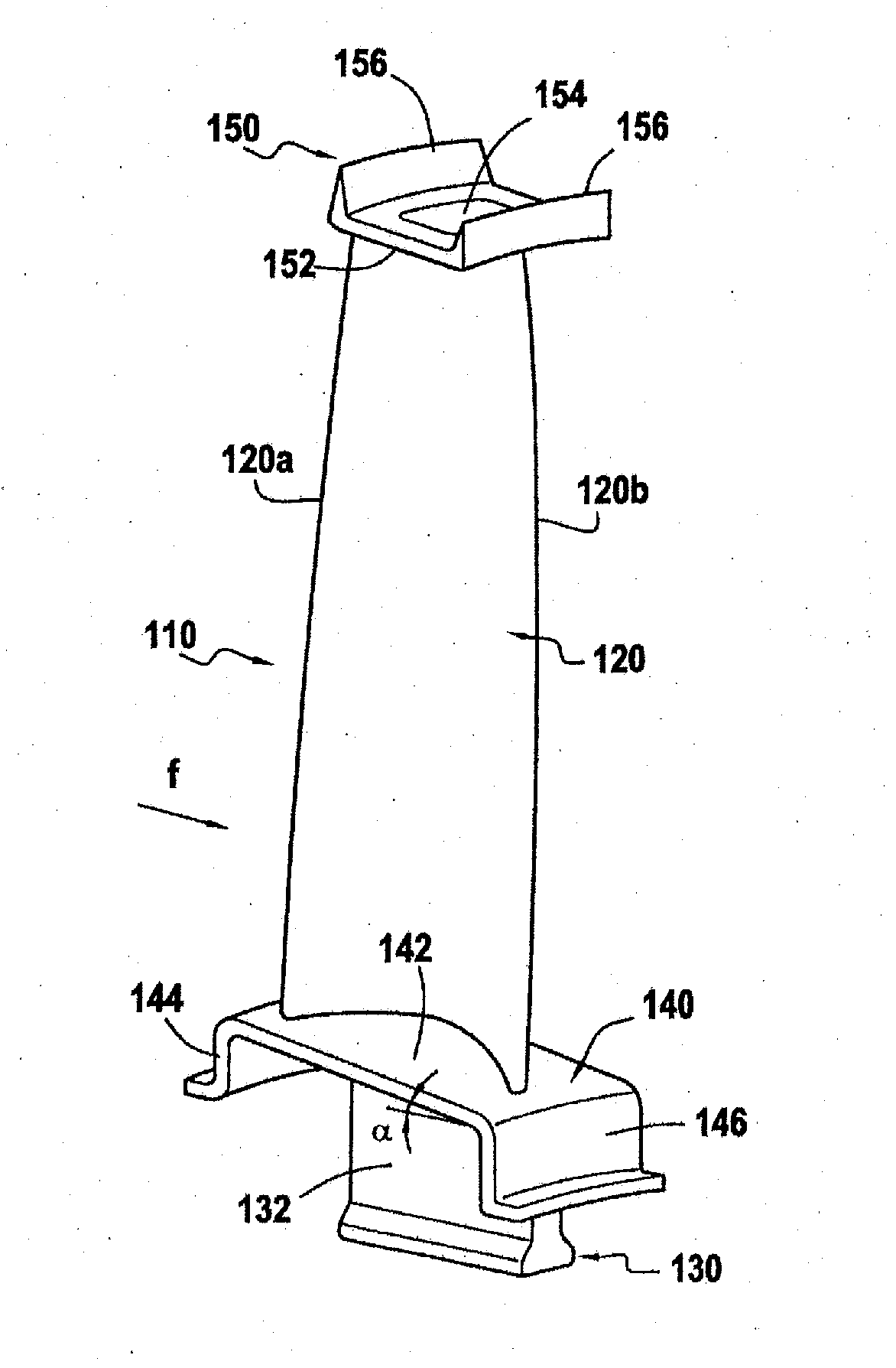
[0087]The method of the invention may be used to fabricate various types of turbomachine blades, for example blades of a rotor disk of a low pressure turbine, which blades have inner and outer platforms incorporated therein, like the blade 110 shown in FIG. 3.

[0088]The blade 110 of FIG. 2 comprises in well-known manner an airfoil 120, a root 130 formed by a thicker portion, e.g. presenting a section in the form of a bulb that is extended by a tang 132, an inner platform 140 situated between the root 130 and the airfoil 120, and an outer platform 150 in the vicinity of the free end of the airfoil.

[0089]The airfoil 120 extends in a longitudinal direction between the inner platform 140 and the outer platform 150 and presents a cross-section in the form of a curved profile of thickness that varies between its leading edge 120a and its trailing edge 120b.

[0090]The blade 110 is mounte...

example 2

Fabricating Hot Nozzle Flaps for an Aeroengine Gas Turbine with Afterburning

[0134]FIG. 17 shows a steerable flap 500 of the kind used for a variable section nozzle in an exhaust channel of a turbine engine having post-combustion.

[0135]The flap 500 comprises a flap body 510 generally in the form of a cylindrical sector extending between two longitudinal edges 511, 512. Stiffener ribs 520, 530 are formed on the convex face of the flap 500. At one longitudinal end 501 of the flap, a plate 540 is fastened to the convex face of the flap between the ribs 520 and 530, the plate 540 supporting eyelets 541, 542 for passing a hinge pin (not shown) for the flap 500. Another plate 550 is fastened to the convex face of the flap and to the ribs 520, 530. The plate 550 is situated between the ribs 520, 530 at a distance from the end 501 and it carries a hinged connection part 552 for connecting to an actuator (not shown) controlling the angular position of the flap. The flap body 510 is in the for...


PUM

PropertyMeasurementUnit
thicknessaaaaaaaaaa
thicknessaaaaaaaaaa
thicknessaaaaaaaaaa

Abstract

A method of fabricating a complex part out of composite material including three-dimensional woven fiber reinforcement densified by a matrix, the method including three-dimensionally weaving a continuous fiber strip including a succession of fiber blanks for preforms of a plurality of parts that are to be fabricated; subsequently cutting individual fiber blanks out from the strip, each blank being a one-piece blank; shaping a cut-out blank to obtain a one-piece fiber preform having a shape that is close to the shape of a part that is to be fabricated; consolidating the preform in the desired shape; and densifying the consolidated preform by forming a matrix by chemical vapor infiltration.

Description

BACKGROUND OF THE INVENTION[0001]The invention relates to fabricating parts of complex shape out of composite material.[0002]An example of an application of the invention is fabricating parts out of thermostructural composite material for use in the fields of aviation and space.[0003]In well-known manner, fabricating a part out of thermostructural composite material comprises making a fiber preform out of refractory fibers (carbon fibers or ceramic fibers), the preform having a shape that is close to the shape of the part that is to be fabricated, and then densifying the fiber preform with a refractory matrix (of carbon or ceramic).[0004]In order to make the fiber preform, various textile techniques can be used. One known technique consists in making a preform by three-dimensional weaving, or multilayer weaving. Such a method of weaving enables interlacing to be established between layers of yarns so as to give the preform the strength needed to obtain a composite material part havi...

Claims


Application Information

Patent Timeline
Patent Type & Authority Applications(United States)
IPC IPC(8): C23C16/02
CPCB29B11/02Y10S427/10C04B35/52C04B35/565C04B35/6286C04B35/62868C04B35/62873C04B35/62897C04B35/806C04B35/83C04B2235/5244C04B2235/5252C04B2235/614C04B2235/94F01D5/282F01D17/20Y02T50/672F05D2300/601F05D2300/6012F05D2300/614B29B11/16D03D25/005Y02T50/60C04B35/80
Inventor EBERLING-FUX, NICOLASBOUILLON, ERICROUSSILLE, CLÉMENTOTIN, STÉPHANECOUPE, DOMINIQUE
Owner SAFRAN CERAMICS SA
Why Eureka
Try Eureka