
Segmented instrument having braking capabilities

a segmented instrument and braking technology, applied in the field of segmented instruments with braking capabilities, can solve the problems of large space occupied by cables and coil pipes along the elongated body, and achieve the effect of increasing the braking or locking force, stable controllable and/or semi-rigid

Active Publication Date: 2011-12-01
INTUITIVE SURGICAL OPERATIONS INC +1
View PDF14 Cites 34 Cited by
  • Summary
  • Abstract
  • Description
  • Claims
  • Application Information

AI Technical Summary

Benefits of technology

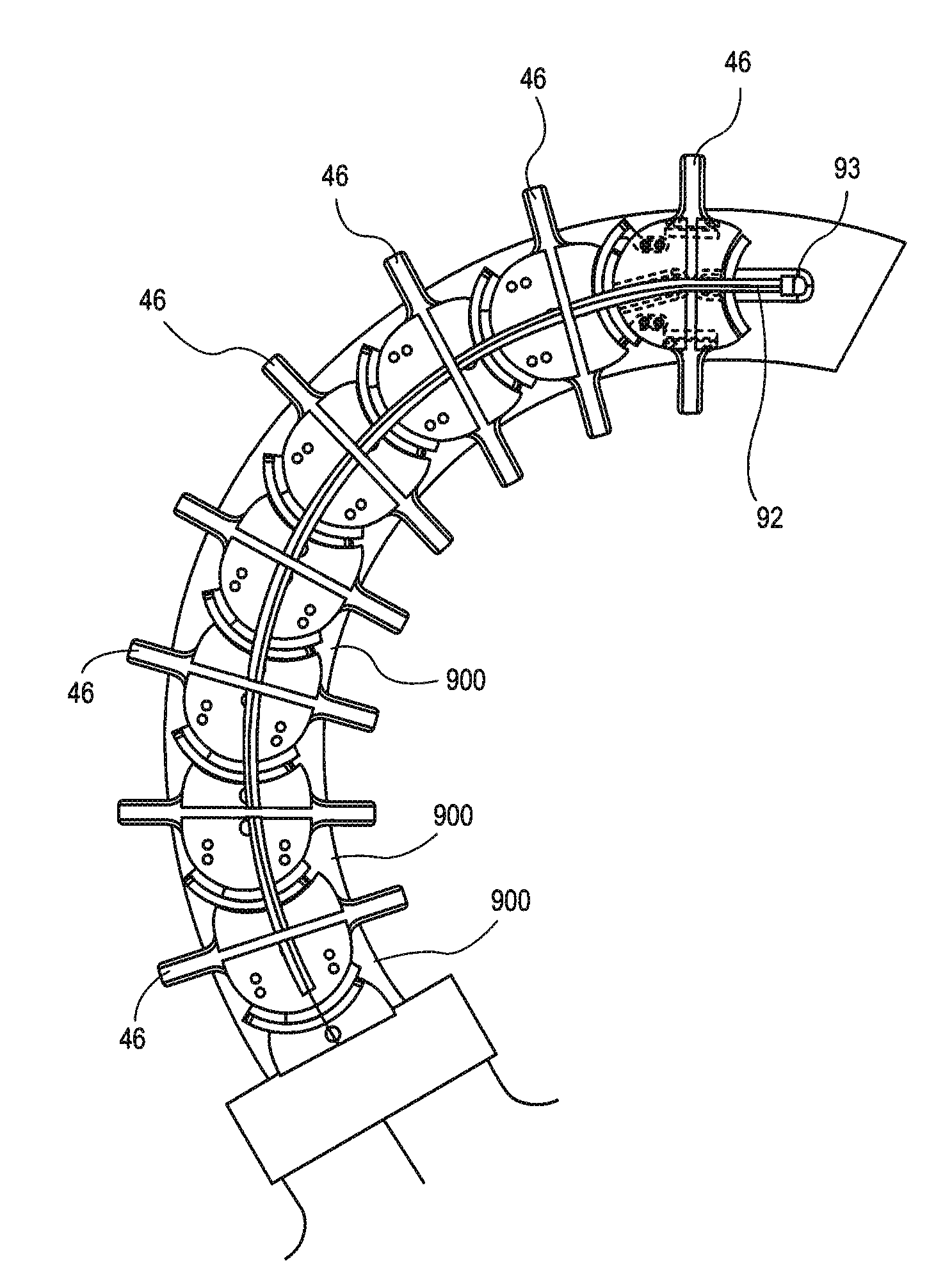
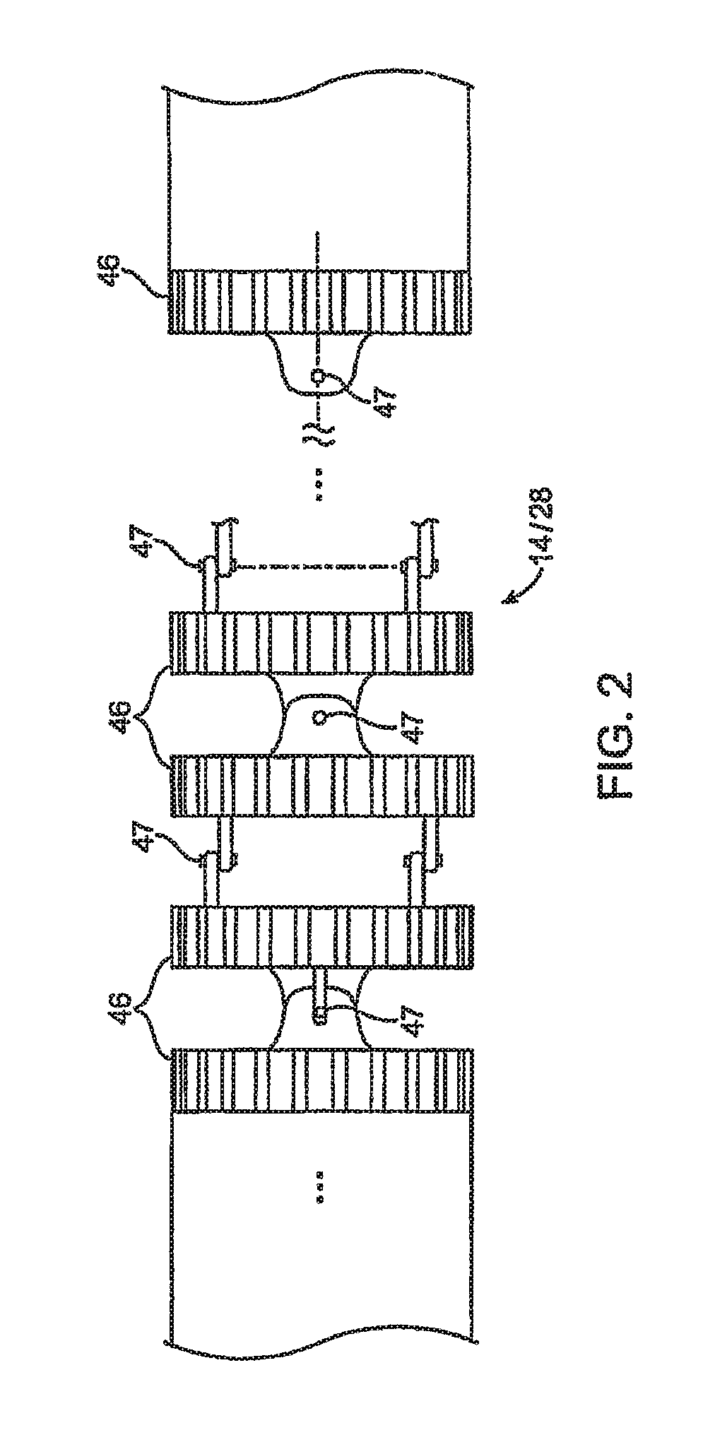
[0005]Embodiments of the present invention may be useful while performing procedures within a patient, such as in natural orifice transluminal endoscopic surgical procedures, to provide a stable controllable and / or semi-rigid platform from which to perform the procedure. In contrast to conventional locking approaches, embodiments of the inventions described herein provide additional frictional surfaces or in some embodiments multiplied frictional surfaces between articulating components. The additional frictional force in turn increases the braking or locking force applied to the instrument. Various embodiments of the present invention provide mechanisms by which the user can selectively rigidize all or a portion of the elongate body through the use of multiple surfaces placed between articulating segments or individual links or vertebra. In addition, while the braking assemblies described herein provide multiplied friction and lock force, they remain capable of articulation when not engaged. In some embodiments, the brake assembly includes the hinge or portion of a hinge or joint used for the articulation of the segmented instrument.
[0006]In one aspect, there is provided a segmented instrument having a plurality of links and at least one lockable and articulatable joint positioned to connect a pair of adjacent links in the plurality of links. In addition, the at least one lockable and articulatable joint being adapted and configured to increase the number of frictional surfaces available between the pair of adjacent links. As described above, cables and coil pipes take up a large amount of space along the elongate body. In one aspect, the brake assembly lies on or in the exterior surface of the segment, hinge or vertebra in order to keep the interior portions of the instrument free.
[0010]The movement of the pair of adjacent links about the hinge is prevented when the brake assembly is engaged. In one aspect, the brake assembly is provided only between a portion of the links in the plurality of links. There are configurations of the braking assembly where one or more are placed wherein the actuation of the brake assembly removes one degree of freedom from a portion of the instrument. In other aspects, a plurality of brake assemblies are coupled to the instrument. In this example, the actuation of the plurality of brake assemblies substantially locks the shape of instrument by locking substantially all of the plurality of links in the instrument. In an alternative configuration, the plurality of brake assemblies are coupled to the instrument wherein actuation of the plurality of brake assemblies substantially removes one degree of freedom from the movement of the segmented instrument.

Problems solved by technology

As described above, cables and coil pipes take up a large amount of space along the elongate body.

Method used


Image

  • Segmented instrument having braking capabilities
  • Segmented instrument having braking capabilities
  • Segmented instrument having braking capabilities

Examples


Embodiment Construction

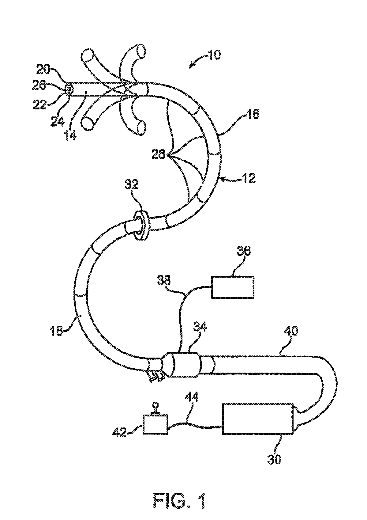
[0028]FIG. 1 depicts a flexible endoscope 10, in accordance with an embodiment of the present invention. Endoscope 10 has elongate body 12 with steerable distal portion 14, automatically controlled proximal portion 16, and flexible and passively manipulated proximal portion 18. The skilled artisan will appreciate that automatically controlled proximal portion 16 may also be flexible and passively manipulated, although it is preferred to provide automatically controlled proximal portion 16. The skilled artisan will also appreciate that elongate body 12 can have only steerable distal portion 14 and automatically controlled portion 16. Fiber optic imaging bundle 20 and illumination fiber(s) 22 may extend through elongate body 12 to steerable distal portion 14, or video camera 24 (e.g., CCD or CMOS camera) may be positioned at the distal end of steerable distal portion 14, as known by the skilled artisan. As the skilled artisan appreciates, a user views live or delayed video feed from v...


PUM


Abstract

One embodiment of present invention is a segmented instrument having braking capabilities that includes an elongate body having a plurality of links and a hinge connecting a pair of adjacent links in the plurality of links. There is also brake assembly coupled to each link in the pair of adjacent links and positioned to span the distance between the pair of adjacent links. Another embodiment of the present invention is a segmented instrument having a plurality of links and at least one lockable and articulatable joint positioned to connect a pair of adjacent links in the plurality of links. In addition, the at least one lockable and articulatable joint is adapted and configured to increase the number of frictional surfaces available between the pair of adjacent links. There are also provided methods for controlling a segmented instrument. Exemplary steps of the method include introducing a segmented instrument into a patient where the segmented instrument has a plurality of links wherein adjacent links are joined by a hinge. Next, there is the step of manipulating the links about the hinges to maneuver the segmented instrument to provide access to a surgical site within the patient. In one aspect, the manipulating step produces a sliding motion between a plurality of complementary shaped components within a portion of a brake assembly between adjacent links. Next there is the step of actuating the brake assembly to substantially prevent movement about the hinge of the links attached to the braking mechanism.

Description

CROSS REFERENCE TO RELATED APPLICATION[0001]This application claims the benefit under 35 U.S.C. 119 of U.S. Patent Application No. 61 / 026,628, filed Feb. 6, 2008, titled “Vacuum Lock Technology”.INCORPORATION BY REFERENCE[0002]All publications and patent applications mentioned in this specification are herein incorporated by reference to the same extent as if each individual publication or patent application was specifically and individually indicated to be incorporated by reference.FIELD OF THE INVENTION[0003]Embodiments of the present invention provide articulating and lockable segmented instruments useful in perform surgical procedures in the body. The instruments described herein may articulate and then be locked into a desired configuration. In addition, there are also embodiments of the brake assemblies that provide articulation capabilities when not engaged and locking capabilities when engaged.BACKGROUND OF THE INVENTION[0004]Guide tubes may be used to support instruments di...

Claims


Application Information

Patent Timeline
Patent Type & Authority Applications(United States)
IPC IPC(8): A61B1/008A61B1/01
CPCA61B1/008A61B1/042A61B1/2736A61B1/0057A61B1/0053A61B1/0055G02B23/2476
Inventor GURUSAMY, JAYSHELLBERGER, CARSON JAYJULIAN, CHRISTOPHER A.OEH, JOSHUA
Owner INTUITIVE SURGICAL OPERATIONS INC
Learn More