Method for reducing a driving power of a vehicle drive

Inactive Publication Date: 2011-12-01
ROBERT BOSCH GMBH
View PDF22 Cites 6 Cited by
  • Summary
  • Abstract
  • Description
  • Claims
  • Application Information

AI Technical Summary

Benefits of technology

[0007]The present invention is based on the finding that the driving power may be reduced, while, at the same time, critical driving situations are avoided, as a function of the driving state, in particular in a driving state in which th

Problems solved by technology

In contrast, the instantaneous driving state does not allow for a reduction in the driving power if the driving state is a pass

Method used


Image

  • Method for reducing a driving power of a vehicle drive
  • Method for reducing a driving power of a vehicle drive

Examples


Embodiment Construction

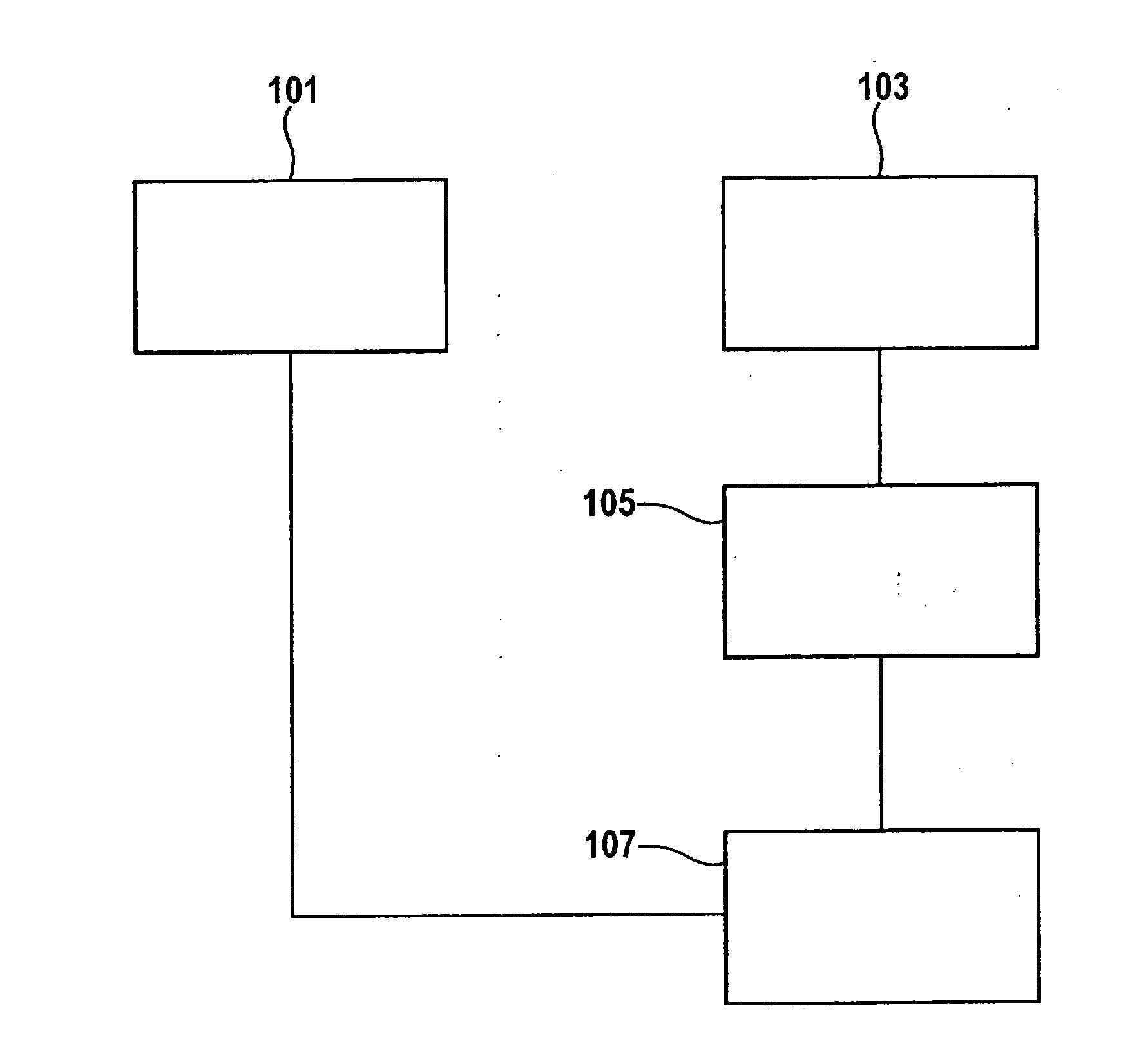
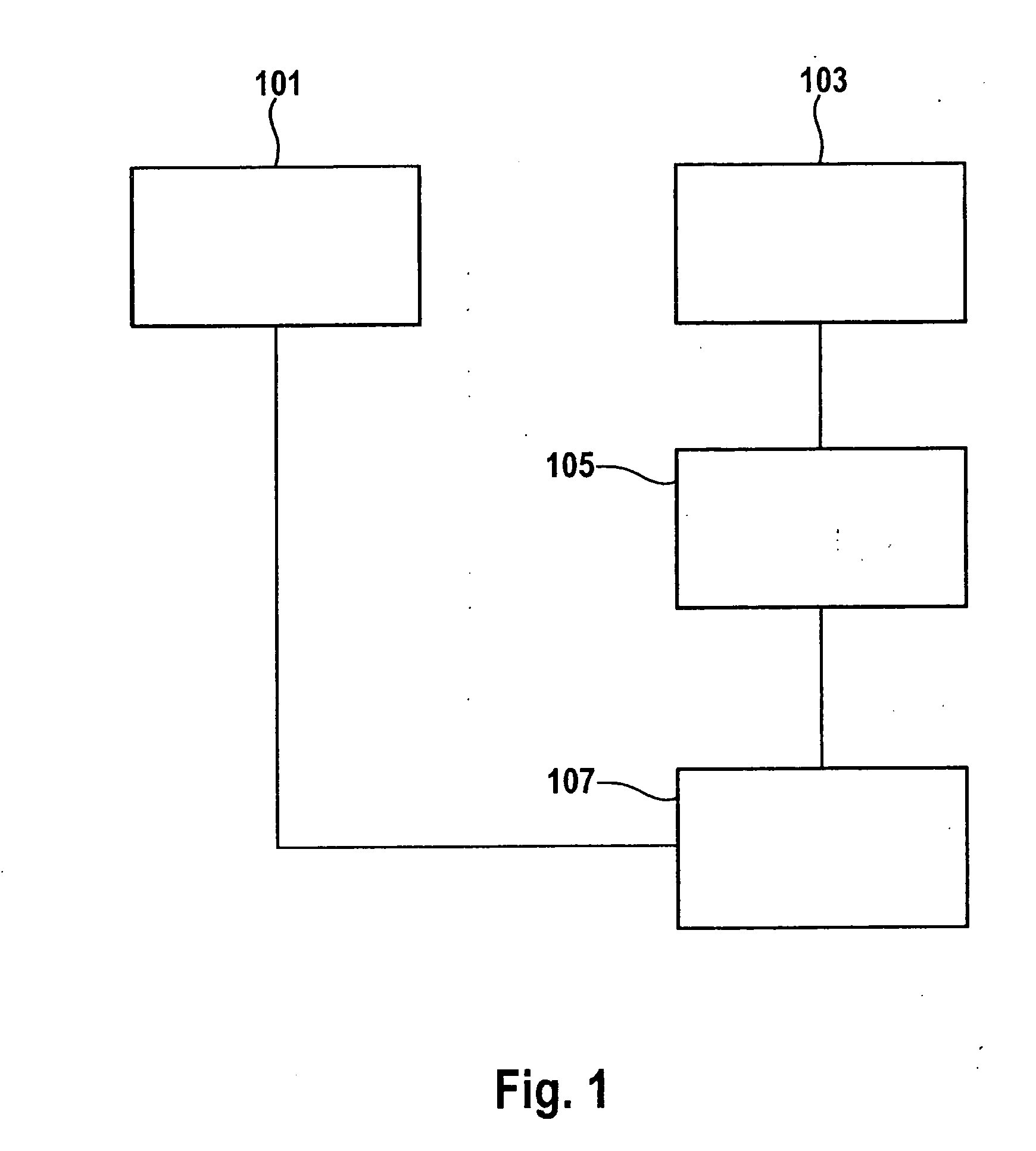
[0023]As FIG. 1 shows, a temperature difference between a temperature of at least one component of the vehicle drive and a temperature threshold value is detected in step 101. At the same time or previously or subsequently, an instantaneous driving state of the vehicle drive, i.e., the driving state in which the vehicle drive is at the moment, is detected in step 103. In step 105, it is established, for example, on the basis of one comparison or multiple comparisons, whether or not the instantaneous driving state allows for a reduction in the driving power. Subsequently, in step 107, the driving power of the vehicle drive is reduced for lowering the temperature of the at least one component in order to increase the temperature difference for providing a temperature reserve, for example, for a subsequent driving state if the instantaneous driving state allows for a reduced driving power. In other words, the driving power is reduced only if it has been established that the instantaneo...


PUM


Abstract

A method for reducing a driving power of a vehicle drive includes detecting a temperature difference between a temperature of at least one component of the vehicle drive and a temperature threshold value, detecting an instantaneous driving state of the vehicle drive, establishing whether or not the instantaneous driving state allows for a reduction in the driving power of the vehicle drive, and reducing the driving power of the vehicle drive for lowering the temperature of the at least one component in order to increase the temperature difference if the instantaneous driving state allows for the reduced driving power.

Description

BACKGROUND OF THE INVENTION[0001]1. Field of the Invention[0002]The present invention relates to power reduction in vehicle drives for lowering temperature.[0003]2. Description of Related Art[0004]The performance of components of a vehicle drive is essentially a function of the heat output or of the temperature of the particular component of the vehicle drive. Thus, for example an electric drive or an energy storage of an electric vehicle or of a hybrid vehicle has a temperature curve which results in the particular component having to be operated at reduced power if its temperature reaches a maximum temperature at which this component may be damaged. This power reduction, also known as derating, presents no problem, as long it is not performed in driving situations in which the driver expects or needs the full driving power, for example, to carry out, for example, a passing maneuver on the oncoming lane or to merge onto a superhighway. Power reduction is critical, in particular in ...

Claims


Application Information

Patent Timeline
IPC IPC(8): G06F19/00F16H61/00F02D28/00B60L15/20B60W10/10B60W30/18
CPCB60L2240/425B60L2200/26B60L2240/485B60L2240/486B60W10/06B60W10/08B60W10/10B60W10/26B60W20/00B60W30/1843B60W2510/0676B60W2510/087B60W2510/107B60W2510/246B60W2520/105B60W2550/402B60W2710/105Y02T10/6291Y02T10/642Y02T10/7258Y02T90/34B60L2240/445B60W50/0097B60W2510/244B60W2556/50Y02T10/62Y02T10/64Y02T10/72Y02T90/40B60W10/04B60W20/15
Inventor FASSNACHT, JOCHEN
Owner ROBERT BOSCH GMBH
Why Eureka
Try Eureka