Sheet Metal Forming Failure Prediction Using Numerical Simulations

a technology of numerical simulation and sheet metal, applied in the field of computer-aided engineering analysis, can solve problems such as tearing and/or fracture, physical material failures are not predicted, and the use of traditional fld is not suitable for us

Inactive Publication Date: 2011-12-01
LIVERMORE SOFTWARE TECH
View PDF12 Cites 15 Cited by
  • Summary
  • Abstract
  • Description
  • Claims
  • Application Information

AI Technical Summary

Benefits of technology

One of the objects of the present invention is to provide an easy to use and observe means that indicates whether a necking failure might occur based on structural responses obtained a numerical simulation.

Problems solved by technology

Localized necking would eventually result into tearing and / or fracture.
To correct the problem, the shape of the forming tool (i.e., die, punch) needs to be modified, which is costly due to production time delay and physical costs.
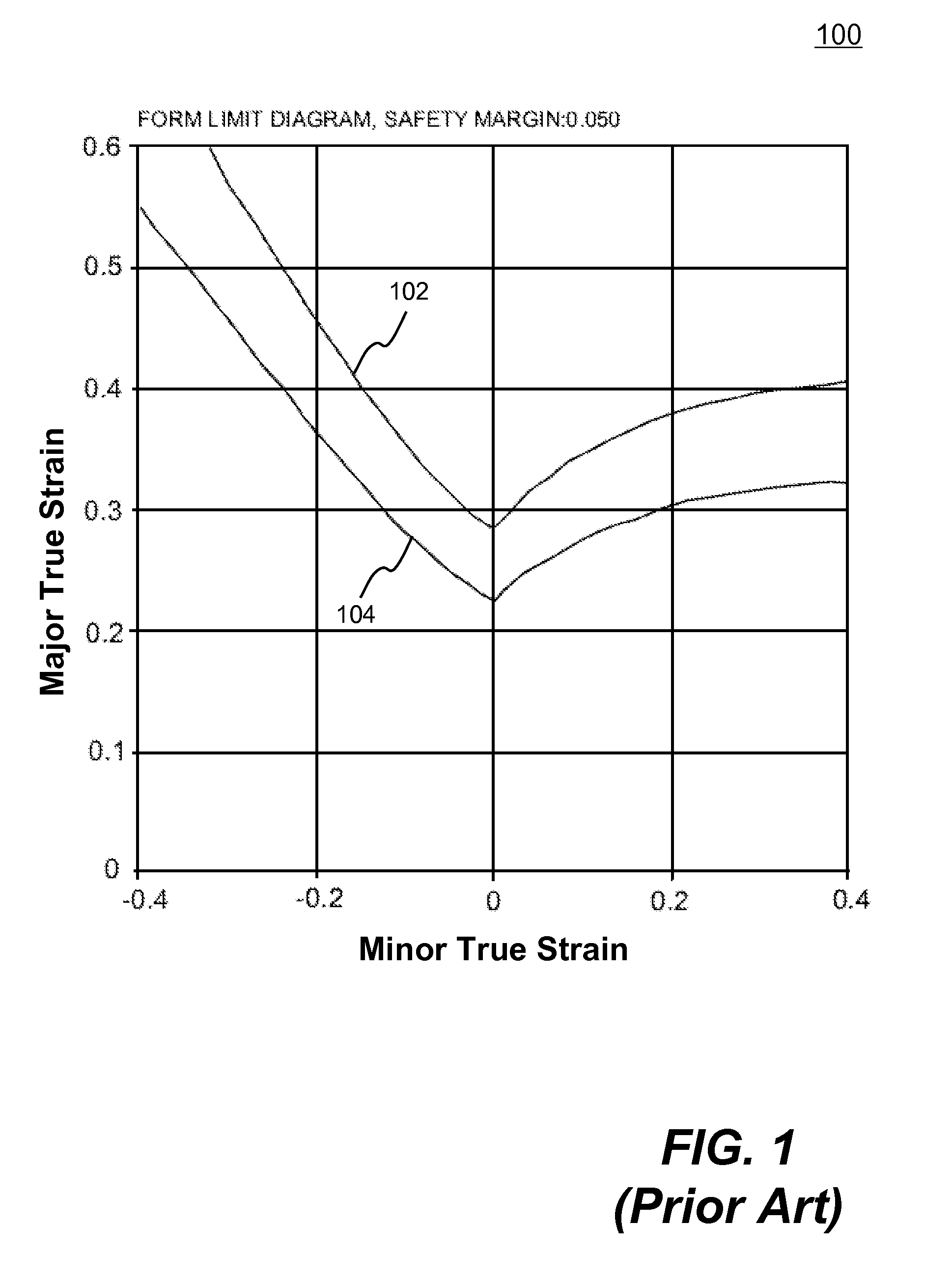
However, there are problems related to using traditional FLD.
As a result, some of the physical material failures are not predicted (i.e., physical part shows failure while the numerical simulation does not).
Furthermore, in multi-stage forming processes, such as drawing followed by flanging, the loading direction will inevitably change.
In order to accurately predict necking failure, a set of FLCs corresponding to various strain path conditions in forming of the part must be provided in a simulation, which is not practical at all.
However, this approach may unnecessarily limit the design space as the safe margin line is much lower than the original FLC.

Method used


Image

  • Sheet Metal Forming Failure Prediction Using Numerical Simulations
  • Sheet Metal Forming Failure Prediction Using Numerical Simulations
  • Sheet Metal Forming Failure Prediction Using Numerical Simulations

Examples


Embodiment Construction

In the following description, numerous specific details are set forth in order to provide a thorough understanding of the present invention. However, it will become obvious to those skilled in the art that the present invention may be practiced without these specific details. The descriptions and representations herein are the common means used by those experienced or skilled in the art to most effectively convey the substance of their work to others skilled in the art. In other instances, well-known methods, procedures, components, and circuitry have not been described in detail to avoid unnecessarily obscuring aspects of the present invention.

Reference herein to “one embodiment” or “an embodiment” means that a particular feature, structure, or characteristic described in connection with the embodiment can be included in at least one embodiment of the invention. The appearances of the phrase “in one embodiment” in various places in the specification are not necessarily all referrin...


PUM


Abstract

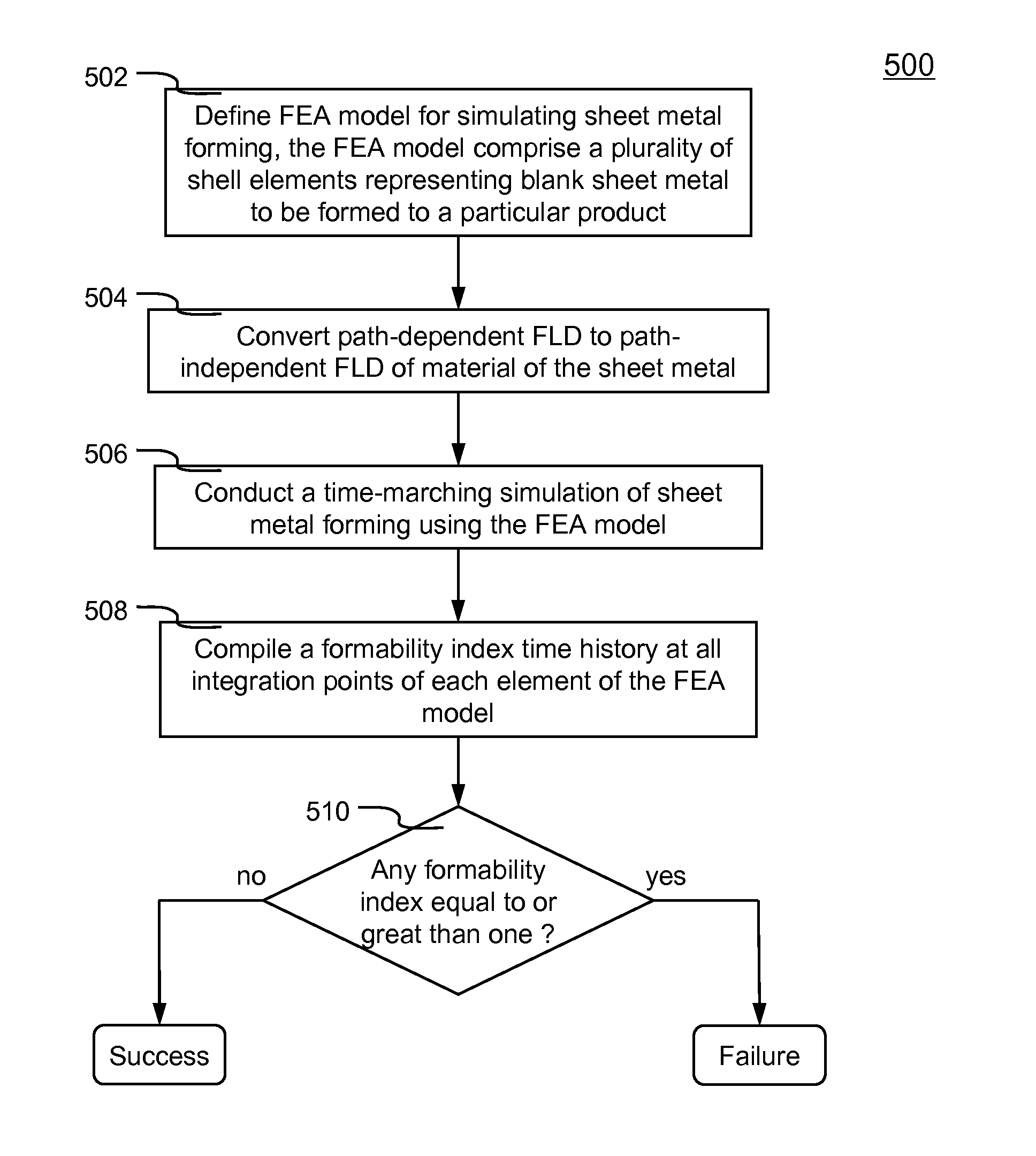
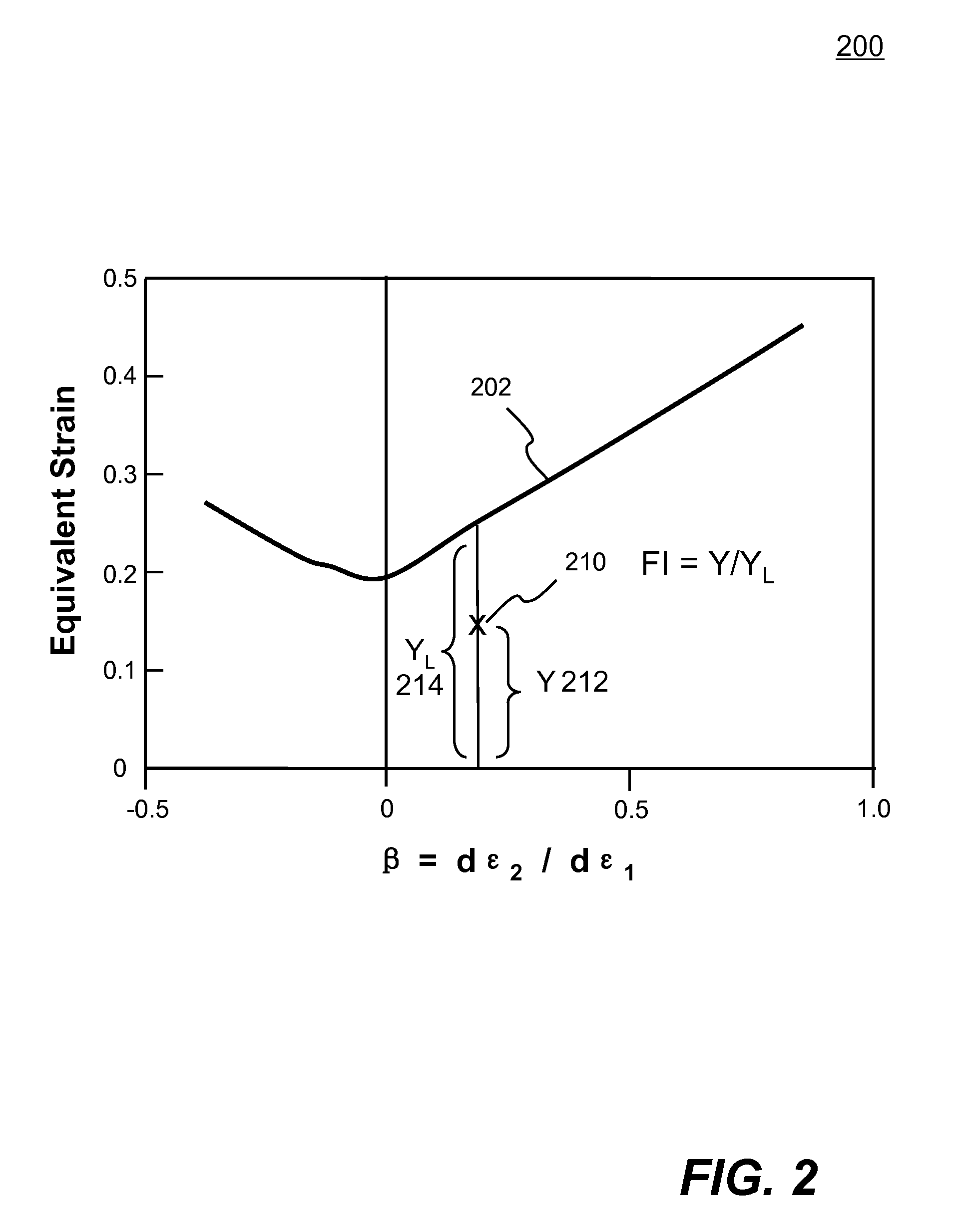
Systems and methods of predicting sheet metal forming failure using numerical simulations (e.g., finite element analysis) are disclosed. A FEA model is defined for a particular sheet metal forming process. Blank sheet metal is modeled with a plurality of shell elements. Additionally, a deformation path-dependent forming limit diagram (FLD) is converted to a path-independent FLD. A time-marching simulation of the sheet metal forming process is conducted using the FEA model. At each solution cycle, equivalent strain at each integration point of shell element is checked against the corresponding forming limit strain value of the path-independent FLD. The ratio of the equivalent strain and the forming limit strain is defined as formability index. A time history of the formability index of each shell element is saved into a file and displayed to a monitor upon user's instructions. When a particular element's formability index reaches one or higher, a localized necking is predicted.

Description

FIELD OF THE INVENTIONThe present invention generally relates to computer aided engineering analysis, more particularly to predict sheet metal forming failure using numerical simulation with finite element analysis (FEA).BACKGROUND OF THE INVENTIONMany of metal parts are manufactured via sheet metal forming. One of the most used sheet metal forming processes is deep drawing, which involves a hydraulic or mechanical press pushing a specially-shaped punch into a matching die with a piece of blank sheet metal in between. Exemplary products made from this process include, but are not limited to, car hood, fender, door, automotive fuel tank, kitchen sink, aluminum can, etc. In deep drawing, the depth of a part being made is generally more than half its diameter. As a result, the blank is stretched and therefore thinning in various locations due to the geometry of the part. The part is only good when there is no structural defect such as material failure (e.g., cracking, tearing, wrinklin...

Claims


Application Information

Patent Timeline
Patent Type & Authority Applications(United States)
IPC IPC(8): G06F17/50G06F17/11
CPCG06F17/5018Y02T10/82G06F2217/42G06F2217/16G06F30/23G06F2111/10G06F2113/24
Inventor ZHU, XINHAIZHANG, LI
Owner LIVERMORE SOFTWARE TECH
Why Eureka
Try Eureka