
Reducing Electromagnetic Interference in a Received Signal

Active Publication Date: 2011-12-01
MARVELL ASIA PTE LTD
View PDF33 Cites 31 Cited by
  • Summary
  • Abstract
  • Description
  • Claims
  • Application Information

AI Technical Summary

Benefits of technology

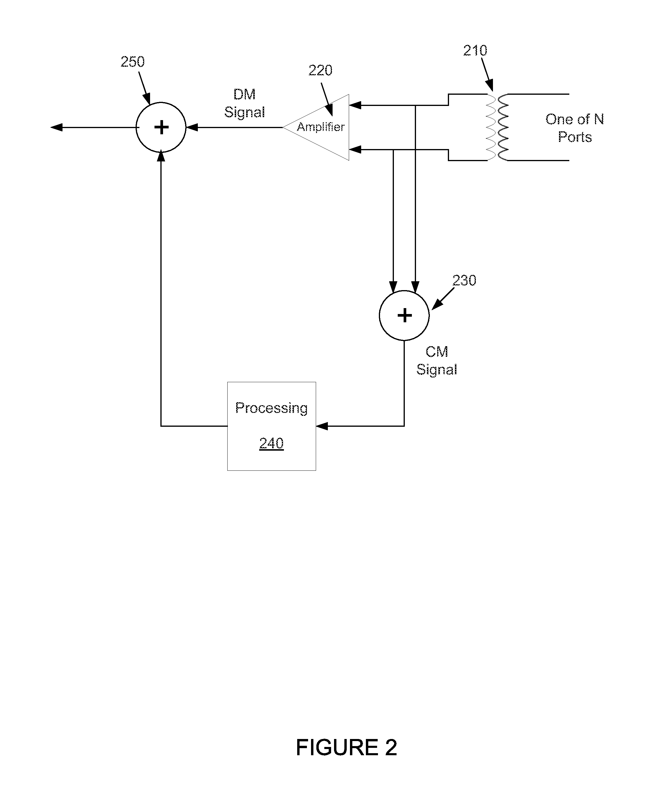
[0008]An embodiment includes a method of reducing electromagnetic interference of a received signal. A signal is received over at least two conductors. A common-mode signal is extracted from the at least two conductors. The common-mode signal is processed and summed with the received signal, thereby reducing electromagnetic interference of the received signal.
[0009]Another embodiment includes a transceiver. The transceiver includes a receive port operative to receive a signal over at least two conductors, means for extracting a common-mode signal from the at least two conductors, a processor operative to process the common-mode signal, and a canceller operative to sum the processed common-mode signal with the received signal to reduce electromagnetic interference of the received signal.
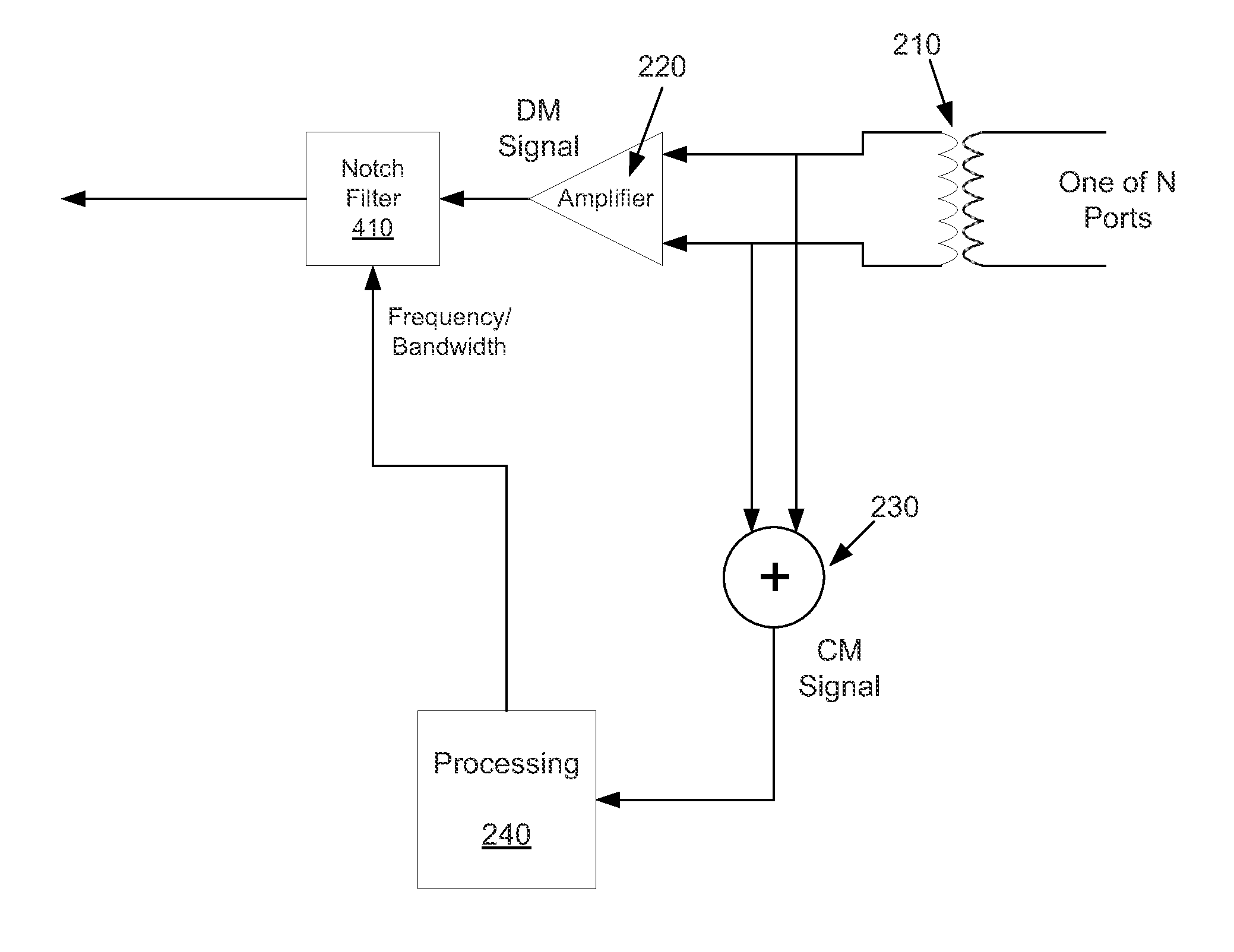
[0010]Another embodiment includes another method of reducing electromagnetic interference of a received signal. A signal is received over at least two conductors. A common-mode signal is extracted from the at least two conductors. Electromagnetic interference of the received signal is reduced using notch filtering, wherein the notch filtering is based at least in part on the processed common-mode signal.
[0011]Another embodiment includes another method of reducing electromagnetic interference of a received signal. A signal is received over at least two conductors. A common-mode signal is extracted from the at least two conductors. Electromagnetic interference of the received signal is reduced using slicer error feedback, wherein the slicer-error feedback filtering is based at least in part on the processed common-mode signal.

Problems solved by technology

However, the immunity of current Ethernet systems (higher frequency systems) to EMI is not sufficient, and the EMI can cause the link to fail, and be unable to transmit data.
Suppression of EMI can be extremely challenging since the EMI usually appears at unknown times and with unknown frequency, bandwidth, power, modulation, duration, etc.
Additionally, suppressing the EMI when the link is already transmitting data is extremely difficult since the EMI characteristics need to be determined very fast to be able to cancel the EMI before the link fails.
Moreover, there is no training data to help detect and cancel the EMI since the link is transmitting real traffic.

Method used


Image

  • Reducing Electromagnetic Interference in a Received Signal
  • Reducing Electromagnetic Interference in a Received Signal
  • Reducing Electromagnetic Interference in a Received Signal

Examples


Embodiment Construction

[0027]As shown in the drawings for purposes of illustration, the invention is embodied in an apparatus and methods for reducing electromagnetic interference of a received signal of a transceiver. The descriptions provided are generally focused on Ethernet transceivers, but the described embodiments can be used in other configurations of transceivers as well. It is to be understood that the electromagnetic signals can take different forms. That is the electromagnetic signals can couple into the receive signals wirelessly, through cables, through circuit boards, and / or through power supplies.

[0028]FIG. 2 shows a block diagram of an example of a transceiver that can utilize the described embodiments for reducing electromagnetic interference of a received signal. This embodiment includes N receiver ports, which as shown, can include a transformer 210. The transformer can be connected, for example, to a pair of copper wires, wherein four transformers are connected to four pairs of wires....


PUM


Abstract

Embodiments of methods and apparatus for reducing electromagnetic interference of a received signal are disclosed. One method includes receiving a signal over at least two conductors, extracting a common-mode signal from the at least two conductors, processing the common-mode signal, and reducing electromagnetic interference of the received signal by summing the processed common-mode signal with the received signal.

Description

FIELD OF THE INVENTION[0001]The invention relates generally to network communications. More particularly, the invention relates to methods and apparatuses for reducing electromagnetic interference in a received signal.BACKGROUND OF THE INVENTION[0002]High-speed networks are continually evolving. The evolution includes a continuing advancement in the operational speed of the networks. The network implementation of choice that has emerged is Ethernet networks physically connected over unshielded twisted pair wiring. Ethernet in its 10 / 100BASE-T form is one of the most prevalent high speed LANs (local area network) for providing connectivity between personal computers, workstations and servers.[0003]High-speed LAN technologies include 100BASE-T (Fast Ethernet) and 1000BASE-T (Gigabit Ethernet). Fast Ethernet technology has provided a smooth evolution from 10 Megabits per second (Mbps) performance of 10BASE-T to the 100 Mbps performance of 100BASE-T. Gigabit Ethernet provides 1 Gigabit ...

Claims


Application Information

Patent Timeline
IPC IPC(8): H04B1/10G06F11/07H04L5/16
CPCH04L25/0276H04L5/16
Inventor MALKIN, MOSHETELLADO, JOSE
Owner MARVELL ASIA PTE LTD
Learn More