Laminate structure with embedded cavities and related method of manufacture

a technology of laminate structures and cavities, applied in the field of optical fibers, can solve problems such as limiting the scope of claimed subject matter

Inactive Publication Date: 2011-12-08
NITTO DENKO CORP
View PDF12 Cites 15 Cited by
  • Summary
  • Abstract
  • Description
  • Claims
  • Application Information

AI Technical Summary

Benefits of technology

[0009]Thereby, an objective of various embodiments of the invention is to alleviate one or more problems described hereinabove not yet satisfactorily addressed by the current arrangements, and to provide a feasible alternative for producing various functional structures such as optically functional structures.
[0040]The utility of the invention generally arises from a plurality of issues depending on each particular embodiment. First of all, both simple and very complex high performance, integrated nano- or micro-scale structures with various functionalities, such as optical structures, fluidic structures (e.g. channels), cooling structures, or lubricant structures, may be embedded within a laminate structure including at least two elements defining at least two layers attached together. The utilized lamination technique may be selected so that the attachment is secure and / or there substantially remain no (unintended) gaps between the laminated elements. Further integrated elements, layers or coatings may be provided on any side of the obtained laminate. In most embodiments, the laminate structure may be manufactured with a relatively simple and low cost industrial scale method. Yet, the embedded structures of the laminate remain protected from external impulses and contamination. Service life of the related products is extended and many of them may be practically maintenance-free.
[0041]Also, multilevel / layer embedded structures may be easily constructed. Internal light-trapping structures utilizing e.g. specific geometrics, refractive indexes and / or materials may be provided for internally reflecting light. Light capture layers effectively capturing and collimating light with a wide range of incident angles may be implemented. The laminate may be applied in connection with integrated electronics, semiconductors, (bio)medical systems, tribological systems, windows, such as window lighting, solar cells, green house illumination, advertising, security applications, automotive and generally vehicle industry, street lighting, general lighting and various signs or plates, such as traffic signs and luminous tags, for instance.

Problems solved by technology

However, this summary is not intended to specifically identify the sole important or, in particular, essential features of the claimed subject matter and thus limit the claimed subject matter's scope.

Method used


Image

  • Laminate structure with embedded cavities and related method of manufacture
  • Laminate structure with embedded cavities and related method of manufacture
  • Laminate structure with embedded cavities and related method of manufacture

Examples


embodiment 302

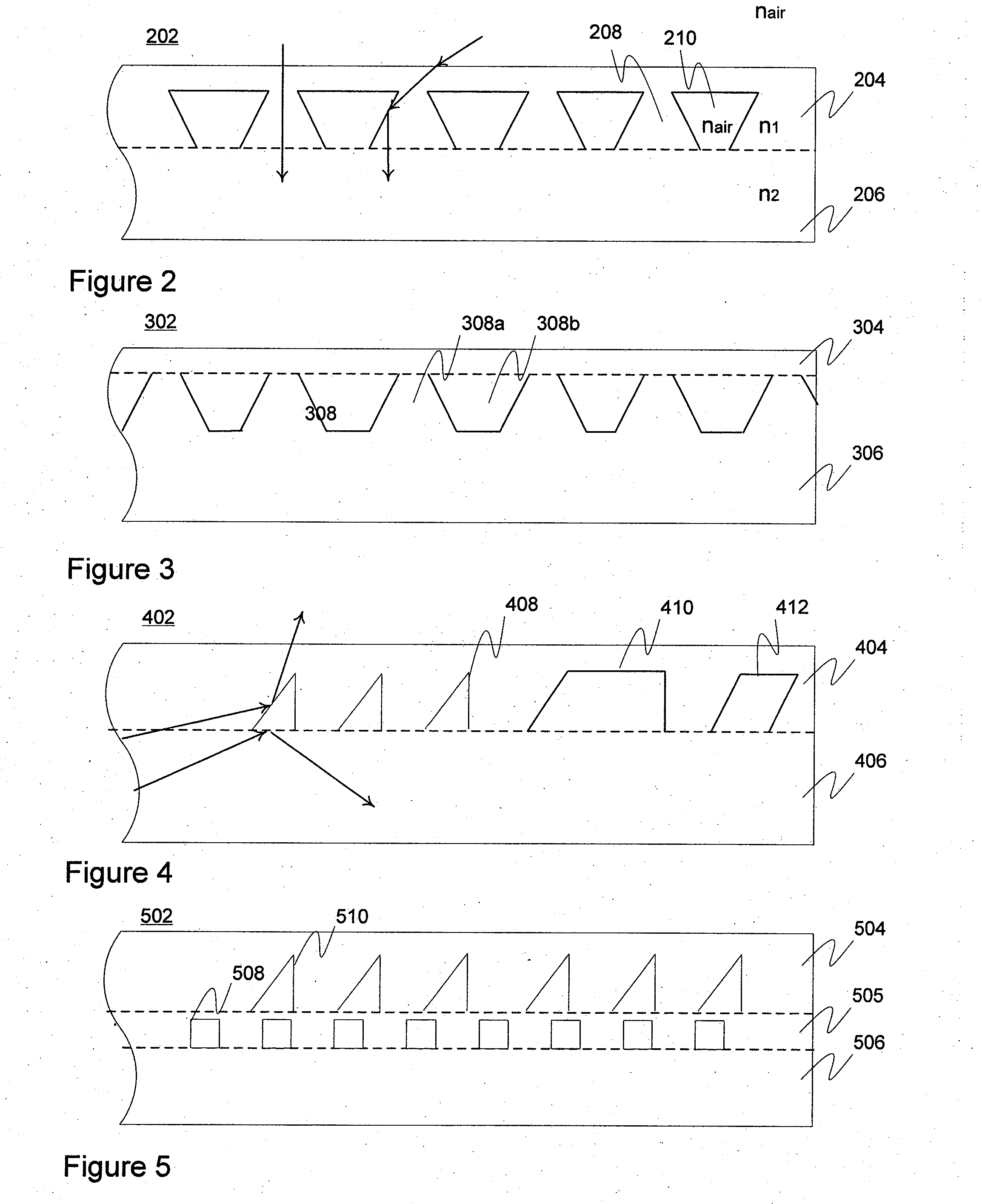
[0080]FIG. 3 discloses another embodiment 302 with two carrier elements 304, 306. In this embodiment, the bottom element 306 contains a surface relief pattern 308 with protrusion 308a and intermediate recess 308b forms, or “profiles”, on top of which a flat top element 304 has been laminated. Again, the established cavities may contain air and / or some other material(s).

embodiment 402

[0081]FIG. 4 discloses an embodiment 402 in which a plurality of different embedded surface relief forms is configured to form a number of embedded surface relief patterns relative to elements 404, 406 laminated together. Triangular 408, trapezoidal 410 and slanted (rectangle or square) 412 forms are shown in the figure. For example, the forms and related patterns may have been configured for outcoupling and / or other type of light redirecting as visualized in the figure by the arrows. Forms of different shape and / or material may be configured so as to provide a common, collective optical function, or they may be utilized for different purposes. A certain embedded surface relief form may have multiple uses depending on e.g. the incident angle and / or face of light. For example, in the figure the leftmost triangle form or cavity has both outcoupling and light trapping functionalities, which has been visualized by the two rays. The established cavities may contain air and / or some other ...


PUM

PropertyMeasurementUnit
sizeaaaaaaaaaa
transmittanceaaaaaaaaaa
height/depthaaaaaaaaaa

Abstract

An integrated laminate structure adapted for application in the context of solar technology, wafer technology, cooling channels, greenhouse illumination, window illumination, street lighting, traffic lighting, traffic reflectors or security films, including a first carrier element optionally including optically substantially transparent material enabling light transmission therethrough, a second carrier element including at least one surface relief pattern including a number of surface relief forms and having at least one predetermined optical function relative to incident light, the second carrier element optionally including optically substantially transparent material enabling light transmission therethrough, the first and second carrier elements being laminated together such that the at least one surface relief pattern has been embedded within the established laminate structure and a number of related cavities have been formed at the interface of the first and second carrier elements. An applicable method of manufacture.

Description

CROSS-REFERENCE TO RELATED APPLICATIONS[0001]This application claims priority to U.S. provisional patent application 61 / 282,818 filed 6 Apr. 2010, the entire contents of the disclosure of which is hereby incorporated by reference.FIELD OF THE INVENTION[0002]Generally, most embodiments of the invention pertain to optics. In particular, however not exclusively, the invention concerns laminate structures with embedded, optically functional cavities and manufacturing thereof.BACKGROUND OF THE INVENTION[0003]Traditionally microstructures, such as microprisms or gratings, of different optics-containing devices, such as lighting apparatuses and electronic apparatuses, have been exclusively produced on surface areas of optically transparent substrates. These structures may have been originally configured to (re)direct, couple or otherwise interact with the incident light in a certain predetermined manner, but positioning thereof on the surface of the material has typically caused a number o...

Claims


Application Information

Patent Timeline
Patent Type & Authority Applications(United States)
IPC IPC(8): G09F13/00B32B3/26G09F7/00B32B37/12B32B38/06B32B3/30B32B37/00
CPCB32B37/12Y10T428/24562B32B38/06B32B38/145B32B37/00B32B37/24F21V5/00H01L31/048Y02E10/52B29D11/00346B29D11/0073H01L31/0547Y10T156/1039Y10T428/24364Y10T156/10B32B37/142H01L31/0543B29D11/00788H01L31/0236G02B6/10G02B6/42B32B17/06
Inventor RINKO, KARI
Owner NITTO DENKO CORP
Why Eureka
Try Eureka