
Insulating finishable panel

a technology of finishable panels and insulation, which is applied in the direction of heat-proofing, walls, coverings/linings, etc., can solve the problems of considerable cost and time for purchasing, transportation, handling and hanging sheetrock or other wall coverings, and reducing the effect of heat dissipation

Inactive Publication Date: 2011-12-08
MCCARY JOHN M
View PDF4 Cites 33 Cited by
  • Summary
  • Abstract
  • Description
  • Claims
  • Application Information

AI Technical Summary

Benefits of technology

[0011]One method of assembling and placing the interior finishable foam panels when there is a reflective face and a need for effective radiant heat reflection or the desire for electrical lines and other utilities to be attached behind the foam panels consists of first locating and attaching electrical lines, cables, outlet boxes, switches or other utilities to the wall surface where the finishable rigid foam panels are to be attached. These utilities should be attached close to the wall and not come out past the wall surface beyond ⅝ inch if possible. Before the finishable rigid foam panels are adhered the location of the outlet boxes, switches and other panel penetrations are cut through the foam panels. Usually 6 to 8 fairly stiff foam air spacers which run in size from approximately ¾ inch round to ½ inch wide short strips that are about ¾ inch thick are applied spaced apart to the reflective / adhering surface of the foam panel. Next, a low rise polyurethane foam style adhesive such as Dow Great Stuff Pro wall adhesive is applied on the wall surface where the foam panel is to be place. Vertical strips of the foam adhesive approximately ½ inches thick are placed about 16 inches apart. The polyurethane style foam usually rises to about twice its' initial applied size. Then the radiant / adhering side of the foam panel is placed on the wall where the adhesive has been applied and pressed toward the wall such that the foam air spacers are slightly compressed and then the panel is released. The process allows the fresh sticky foam adhesive to adhere to the radiant / adhering side surface and the foam air spacer keeps the radiant surface of the foam panel in an approximate ¾ inch spaced relationship from the wall. The ¾ inch air space enables effective radiant reflection; allows for moisture to evaporate and gives room for electrical and other utilities to be placed between the foam panel and the wall surface. Screws or nails may be used to add attaching support to the adherence of the finishable rigid foam panel in conjunction with the foam adhesive, or screws or nails can be the only attaching means.
[0013]The radiant rigid foam panel may be also be used to add insulation to an existing interior wall where it may be hard to add insulation to the existing wall which may be very useful in older structures. In this application one may be giving up about 2 inches of room space but there is the possibility of saving a considerable amount on heating and cooling and even making the structure, in some instances, visually and economically habitable.

Problems solved by technology

Purchasing, handling and applying the furring strips are costly and time consuming.
Secondly to finish the rigid panel there is considerable cost and time for purchasing, transporting, handling and hanging the sheetrock or other wall covering.
In an interior application if a rigid foam panel could be developed that would have a surface on the interior face of the panel that could be taped, joint compound applied, sanded and painted to the desired color and have a finished sheetrock style look and meet code requirements for exposed applications, then there could be considerable cost and time savings.

Method used


Image

  • Insulating finishable panel
  • Insulating finishable panel
  • Insulating finishable panel

Examples


Embodiment Construction

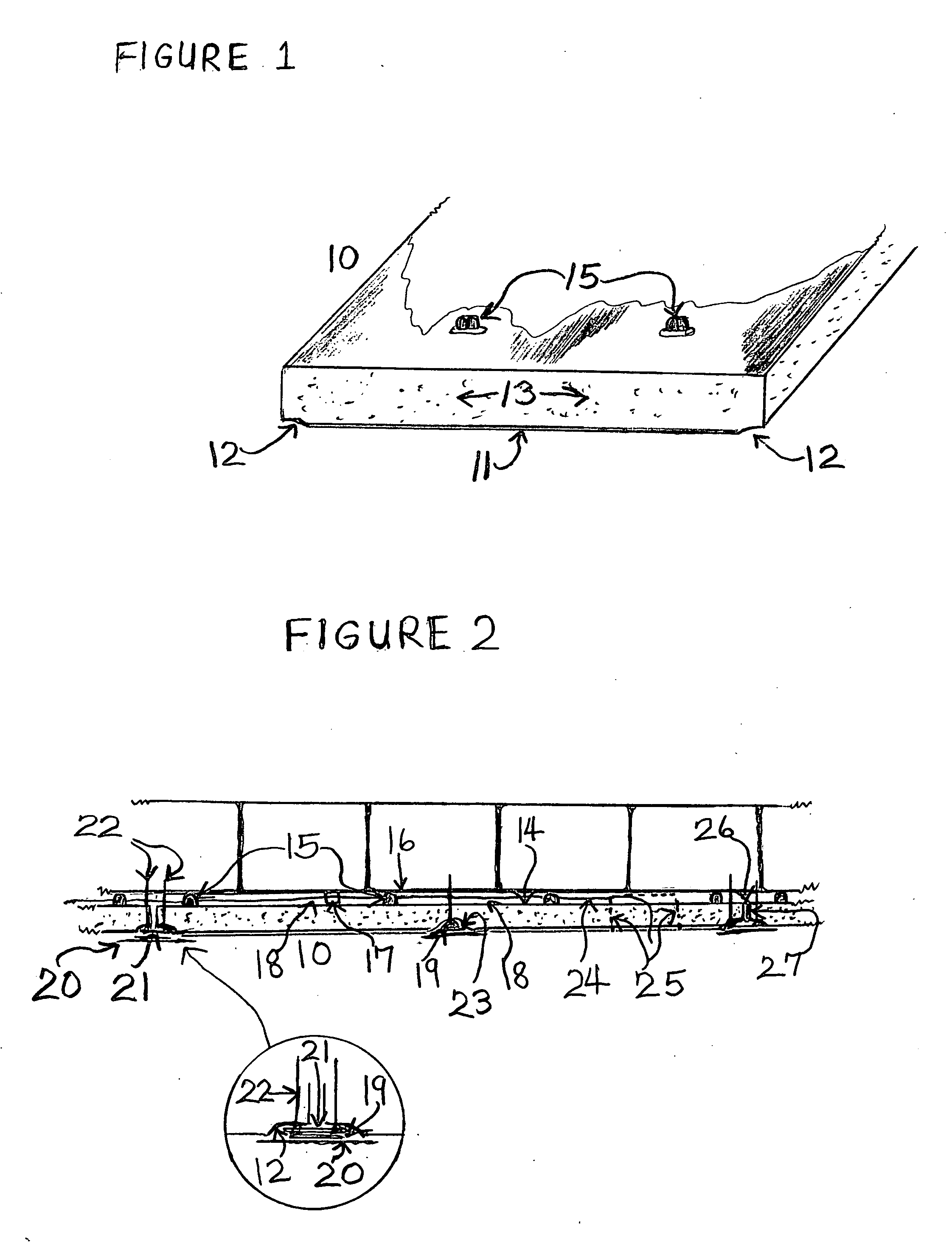
[0021]FIG. 1. shows in a cross sectional perspective view a finishable rigid radiant foam panel 10 with the 6 to 8 mill finishable reinforced surface 11, the tapered long edge indentures 12, the foam core 13, and the radiant reflective surface 14. Shown adhered on the radiant reflective surface 14 are the placed foam air spacers 15 that are spaced as needed depending on the roughness of the wall surface.

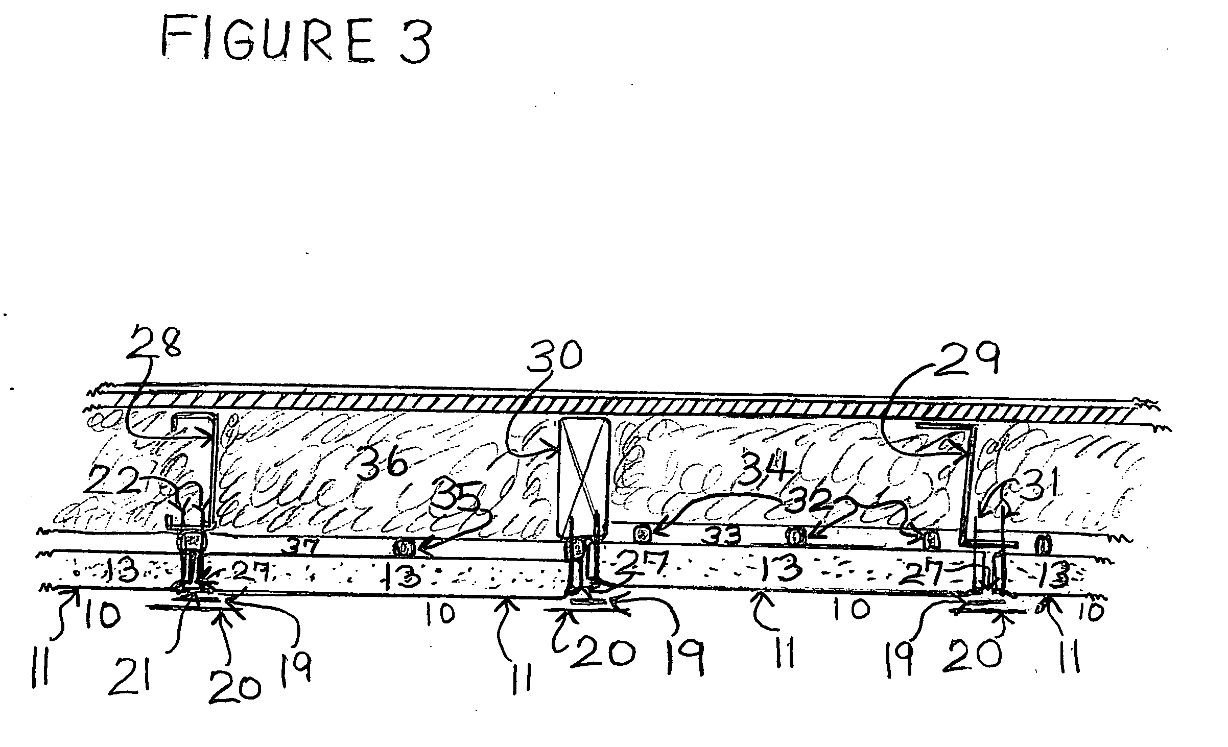
[0022]Shown in FIG. 2 in an overhead cross sectional view is the finishable rigid radiant foam panel 10 attached to a masonry wall or other wall surface 16. Foam air spacers 15 are shown adhered to the panel's radiant reflective surface 14 that have been pressed against the wall surface 16 with the freshly applied approximately ½ bead thick foam adhesive 17. The foam adhesive 17 is shown adhered to the wall surface 16 and the foam panel's reflective surface 14 with the two surfaces kept approximately ¾ inches apart by the foam air spacer 15 creating the air space 18. Sheetrock tape 1...


PUM

PropertyMeasurementUnit
Pressureaaaaaaaaaa
Coloraaaaaaaaaa
Depthaaaaaaaaaa

Abstract

A rigid faced foam cored panel system utilized to produce an insulating finishable surface in interior and exterior applications. The long edges of the rigid foam panels may be indented to form a recessed space for tapping, applying joint compound and assisting in achieving a level finished surface. The inside surface of the rigid foam panel may be radiant reflective with air spacers attached to the reflective surface to produce the needed air space for effective radiant heat reflection. The interior application may entail using the rigid foam panel both as insulation and as a finishable varied color painted or textured wall or ceiling surface. In exterior wall or other exposed surface applications the insulating rigid foam panel may be covered with moisture resistive coverings such as stucco style textures.

Description

FIELD OF THE INVENTION[0001]This invention relates to an assembly of laminates and foam filled sheet products, both decorative and structural, and more particularly it relates to rigid, usually fiber reinforced sheets of foam which are particularly useful in thermal insulating applications and in most applications have a finishable face on at least one side and may have an effective radiant reflective surface upon the other face.BACKGROUND OF THE INVENTION[0002]Foam products have been reinforced and laminated to various facings to give them added strength or other desirable physical properties which the foam is incapable of providing. These foam products have become increasingly useful in the building industry since they possess strength coupled with relatively low density and thus are well suited for use as core materials in sandwich type laminates. The rigid foam laminates can be excellent heat insulators because of their fine closed cell structure. Many different techniques have ...

Claims


Application Information

Patent Timeline
IPC IPC(8): E04C2/22E04B1/70E04C2/20
CPCE04C2/292E04C2/296E04F13/0805E04B2001/7691E04B1/80E04B2/58E04B2/707E04B1/7675E04F13/007E04F13/04E04F13/042E04F13/0803
Inventor MCCARY, JOHN M.
Owner MCCARY JOHN M
Learn More