RAKH Cycle, Boilerless, Airless, Hydrogen Fueled, Closed Cycle, Steam Engine
Inactive Publication Date: 2011-12-08
HURT ROBERT DAVID
11 Cites 9 Cited by
AI-Extracted Technical Summary
Problems solved by technology
Steam engines have proven to be more efficient than modern Internal Combustion Engines, however, size, weight, and safety hazards, underscore some major disadvantages for typical boiler driven steam engines.
Steam engines also suffer cost disadvantages stemming from the use of expensive alloys involved in boiler and condenser construction.
Continuous degradation of heat transfer efficiency caused by water born impurities or combustion products being deposited on heat exchange surfaces also plague the typical steam engine.
They also typically have a flue or smoke stack that contrib...
Abstract
This engine inducts Hydrogen and an inert Quench gas into its combustion chamber, compresses the mixture, and injects Hydrogen Peroxide thru catalytic injectors to burn the Hydrogen in the dissociated oxygen that is liberated. Exhaust flows into a Gas Drier/Condenser (GD/C), which removes exhaust steam. Non-condensable gasses are returned to the engine intake in a closed loop where hydrogen is continuously added via a constant pressure regulator to replace burned Hydrogen. Presence of the Quench gas in the mixture effectively reduces total hydrogen available for combustion. This engine could not work as a closed cycle without the GD/C, which contains a pressurized water trap that allows free flow of recycled non-condensable gasses thru that trap, but condenses steam as it passes thru one ceramic plate and comes into direct contact with pressurized water trapped between the ceramic plates. The pressurized water trap separates the GD/C's inlet from its outlet.
Application Domain
Non-fuel substance addition to fuelInternal combustion piston engines +2
Technology Topic
Water trapInjector +8
Image
Examples
- Experimental program(1)
Example
[0015]FIG. 1 GENERIC SCHEMATIC OF PERTINENT RAKH CYCLE ENGINE COMPONENTS
[0016]FIG. 2 DETAILED INJECTOR DRAWING
[0017]FIG. 3 UPPER INJECTOR BODY DETAIL
[0018]FIG. 4 LOWER INJECTOR BODY DETAIL
DETAILED DESCRIPTION OF THE PREFERRED EMBODIMENT
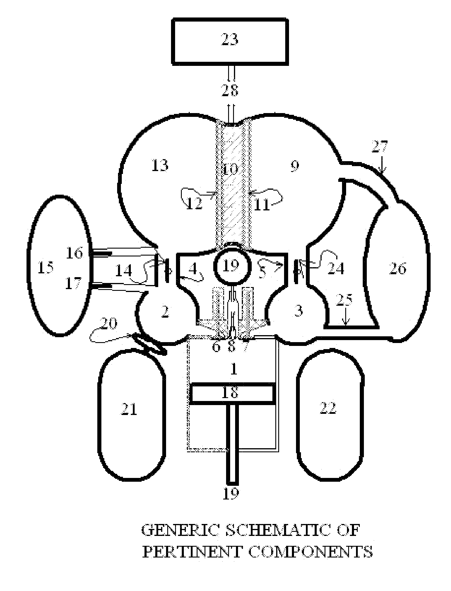
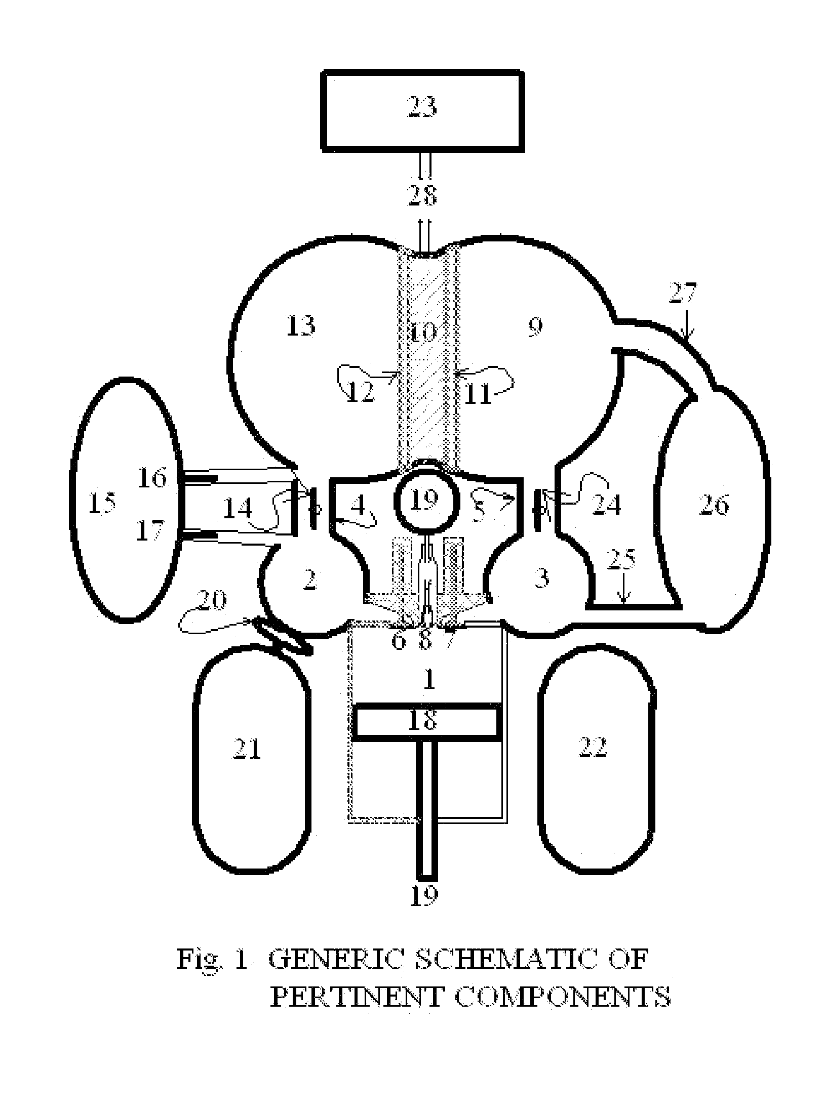
[0019]FIG. 1 illustrates a simplified schematic of the preferred embodiment of the present invention as a piston and cylinder type engine. Piston 18 is connected to a typical crankshaft (not shown) by a connecting rod 19 in a typical piston engine arrangement that converts oscillating motion to rotary mechanical energy that performs the output work of the RAKH engine. The crankshaft also returns some of the rotary mechanical energy thru the connecting rod 19 to suck in a charge of fuel and subsequently compress that intake charge. This detailed description assumes as an arbitrary starting point, the intake of Hydrogen and Helium from the intake manifold 2 thru intake valve 6 into the combustion chamber 1. The Helium is circulated thru the closed system loop, and is never lost from the closed loop system. The pressure of the Helium is fairly constant unless it is pumped out of the system into the Quench gas storage tank 15, which operation will not be described until later, but that Quench gas storage tank is normally isolated from the closed loop system by closed valves 16 and 17. Hydrogen is consumed in the engine and is constantly added to the intake manifold 2 from Hydrogen supply tank 21 via a variable pressure regulator 20, which maintains the intake manifold pressure at whatever pressure setting is established by an engine control module (not shown). For the sake of an initial condition setting, let us assume that the partial pressure of the Helium in the intake manifold 2 is 10 psia, and the regulator 20 is initially set to 15 psia. The regulator 20 attempts to provide 5 psia of hydrogen to the intake manifold 2, for an overall pressure of 15 psia. The Piston 18 draws in a charge of the pressurized mixture from the intake manifold 2 when the piston 18 is pulled down the cylinder with the intake valve 6 opened and the exhaust valves 7 closed by the engine control module in response to a timing signal derived from the position of the crankshaft and the engine's load requirements. Near the bottom of the intake stroke, while the engine is operating in four stroke power mode, the intake 6 and all exhaust 7 valves are both closed near the point where the crankshaft begins to force the piston 18 up via connecting rod 19 and compress the hydrogen and helium with a full intake charge in the combustion chamber 1. Near top dead center, with intake and exhaust valves still closed, a throttled pulse of Hydrogen Peroxide, under control of an engine control module (typically a computerized electronic control module not subject to any claims in this patent), is squirted into the injector nozzle 8 where a catalyst 113 starts the release of available Oxygen from the Hydrogen Peroxide. Both volume and timing are variables that will be adjusted by that engine control module, according to the current load requirements. The Oxygen released from the Hydrogen Peroxide, burns the Hydrogen, as much as it can. The combustion of the hydrogen creates superheated steam. The exothermic release of Oxygen creates heat and steam also. The superheated steam created from the combustion of Hydrogen in oxygen and the excess heat will help convert any remaining water from the diluted Hydrogen Peroxide into steam also. There will be Pressure exerted upon the piston 18 by the steam, which forces the piston 18 down in a power stroke that recovers significantly more energy than the amount consumed in first inducting and then compressing the Hydrogen and Helium. There will be enough mechanical energy created and partially stored in a flywheel (also not shown) connected to the crankshaft to carry the piston past bottom dead center and cause the piston to travel back up the cylinder with one or two exhaust valves 7 opened by the electronic control module to force the exhaust out of the combustion chamber 1 and into the exhaust manifold. At the end of the exhaust stroke, the exhaust valve(s) will be closed and the intake stroke can start all over again in a continuing 4 stroke cycle at moderate engine loads. Alternatively, as the temperature of the combustion chamber increases all valves can be closed by the engine control module near the end of the exhaust stroke, and a squirt of water thru the outer injector water passages 111 will be admitted to cool the combustion chamber as the heat of the cylinder and piston flashes the water into steam with another power stroke and exhaust stroke inserted to cool the engine as needed. Materials used in the preferred embodiment of the cylinder block of this engine would be ceramic or tungsten, able to withstand relatively higher temperatures than most piston engines without permanent deformation from overheating. It is highly desirable to run this engine without cooling water in a water jacket that is cast into the engine block.
[0020]Exhaust travels from the exhaust manifold 3 thru the exhaust duct 5 into a Gas Drier/Condenser (GD/C) inlet 9. The pressure differential of exhaust gasses entering the GD/C inlet 9 and being evacuated from the GD/C outlet 13 by the intake pumping action of the engine drawing a vacuum on the intake manifold with the throttle butterfly valve 14 open, allows communication of that vacuum to the GD/C outlet 13 via the inlet duct 4, causing non-condensable exhaust gasses to pass thru the two low restriction ceramic plates 11 and 12, and the pressurized water 10 trapped between those plates. Steam and Non-condensable Gasses freely pass thru the trap, but the water cannot escape. When steam hits relatively cool trap water that is maintained well below the saturation temperature for the existing exhausted steam pressure, it will condense immediately, imparting latent heat of vaporization into the water 10. Helium and any remaining Hydrogen, present in the exhaust, will see very little restriction in their flow posed by the porous ceramic 11&12 and water 10, which comprise the water trap. It is true that some vapor pressure of the hot trap water 10 will escape thru the outlet side ceramic plate 12 and the outlet gasses will not be perfectly dry. The cooler the trap water is, the dryer the Condenser outlet gasses will be. The preferred embodiment will use expansion of compressed Hydrogen to help cool the water used in the water trap. An ammonia bottoming cycle would be desirable to power accessories. When the engine control module detects a net drain on batteries, the power can be increased by closing the intake duct throttle butterfly valve 14 and opening the Quench gas storage tank's inlet valve 16. The tank will pressurize with non-condensable gasses that exit the GD/C outlet 13. If the Quench Gas storage tank 15 is about the same size as the GD/C, about half of the non-condensable gasses, mostly Helium, should exit the closed loop system. After gas flow into the Quench Gas storage tank subsides, the partial pressure of Helium in the closed loop system should be about half of the initial value (about 5 psia), within only a few seconds. The Hydrogen regulator should make up the difference in pressure from 15 psia by admitting Hydrogen to 10 psia. The Quench Gas storage tank inlet valve 16 can then be closed and the intake duct butterfly valve 14 can be reopened. The partial pressure of the Helium will continue at about 5 psia until the high power (“turbo mode”) is no longer needed. At that point of reduced power needs, the butterfly valve can be closed again at the same time the Quench tank outlet valve 17 is opened, sucking Helium back into the closed loop and nearly emptying the Quench gas storage tank 15. The partial pressure of Helium will once again return to approximately 10 psia, and the Hydrogen regulator 20 will reduce the supply of Hydrogen to the system to a partial pressure of about 5 psia. The electronic control module will initially “dead reckon” the maximum amount of Hydrogen Peroxide that can be injected so that no excess oxygen is produced in the combustion chamber, which might otherwise make it into the exhaust without enough Hydrogen in the combustion chamber to use up all of the oxygen. After the initial “dead reckoning” guess at the maximum amount of Hydrogen Peroxide that should be injected for maximum power, Oxygen Sensors in the exhaust path or in the water trap can be used to reduce the maximum Hydrogen Peroxide injection amount. Increasing the amount of hydrogen in the combustion chamber is very much like the effect of turbo charging an engine, without the significant increase in backpressure on the exhaust system incumbent with turbo charging. The net result of both is to increase the amount of fuel that can be burned inside the combustion chamber. The simplicity of the described “turbo charging” effect in the RAKH Cycle Engine is quite evidently much easier and certainly less mechanically burdensome. The technique of changing the 4 stroke operation of the RAKH Cycle Engine to 2 stroke operation should be simple enough for any reasonably proficient automotive engineer to discern that I will not bore the reader with those details, understanding that the engine control module manipulates the valves and injectors appropriately. A crankcase vent tube (not shown), which simply vents the cylinder at a point below the piston and leads to the exhaust side of the closed loop, adds no challenge to the system. The fact that blow-by is not toxic or burdensome to the RAKH Cycle Engine, allows us to consider omitting the rings in the preferred embodiment since the preferred implementation of this engine is to run it only at a fairly constant high operating speed after startup or shut it off when batteries are sufficiently charged. The engine is either off or it is running at high operating speed, typically 1800 rpm for a four pole 60 Hz AC generator. Engines without rings don't usually idle very well.
[0021]The Hydrogen Peroxide storage tank 22 can contain high concentration Hydrogen Peroxide that is mixed with water derived from a Radiator 23 via a Pump/Mixer 19. A considerable amount of heat must be removed from the water trap by the Radiator 23. The tubes delivering water from the Radiator and those from the Hydrogen Peroxide tank 22 to the Injector Pump/Mixer 19 are not shown in the schematic, but the Radiator Inlet Tube 28 allows outflow of water from the Water Trap 10 to the Radiator 23. There may be no coolant for the RAKH Cycle Engine. The Upper Cylinder Walls and Head can be made of Tungsten metal. When the temperature exceeds a certain limit, the Engine Control Module will manipulate valve operation to insert occasional 6 cycle engine cooling operation via direct injection of water immediately after the exhaust stroke. This Water injection creates low temperature steam from the heat of the cylinder walls, which expands doing work with another power stroke, followed by another exhaust stroke.
[0022]FIG. 2 shows details of the Injector 8. All reference numbers are three digit numbers, except the Injector itself which is still given reference number 8 in both FIG. 1 and FIG. 2. The water jacket bleed orifices 105 and 102, continuously leak a very small amount of water from the water trap to keep the injector cooled and can be pulsed to spray directly onto the upper cylinder walls via an Anti-Bypass Valve (not shown) that closes and inhibits pulse bypass at Top Dead Center for on any given stroke. Pulses are normally bypassed unless the Anti-Bypass valve is closed by the Engine Control Module using input from an over-temperature sensor. Cooling water can be added at Top Dead Center on any stroke, but results in wasted efficiency if it is injected on the Intake Stroke during 4 stroke, or 6 stroke operation of the RAKH Cycle Engine. Extra water injected for the power stroke in 4 stroke operation can also cool the cylinder somewhat. Even more cooling results however, if the water is injected near top dead center after the exhaust valve closes and a secondary power stroke and exhaust stroke are added, totaling 6 strokes. Although the secondary power stroke occurs at a much lower temperature, because there is no combustion involved, and very little high pressure gas is left in the cylinder when the water that is squirted into the combustion chamber converts to steam, it adds to the efficiency of the RAKH Cycle Engine by direct cooling of the cylinders thru latent heat of vaporization of water and the resultant steam is used for a small increment of extra power without needing more fuel. Most internal combustion engines waste this heat by external water jackets and a radiator. The high temperature exhaust from four stroke operation should be used in an optional bottoming engine 26 with exhaust ducted to the intake via bottoming intake duct 25 and then exhausted at a much less energetic pressure and temperature state via bottoming exhaust duct 27 into the GD/C. The bottoming engine can be bypassed or forced into operation by opening or closing the butterfly valve 24 in the RAKH Cycle Engine exhaust duct 5.
[0023]The Injector Upper Body Detail in FIG. 3 shows a one way valve 100 which lets Hydrogen Peroxide in but seals against reverse flow after the pump pulse terminates. The one way valve has a coil return spring 102, which seats the valve and centering fins 101 that keep the valve positioned properly. Some Peroxide is held inside the injector body within its inert, non-catalytic, chamber 107. Cooling water is allowed to dribble into the injector thru injector water inlet holes 105 drilled around the circumference of the injector as needed. They intersect injector cooling water passage ways 111 drilled vertically, nearly the full length of the injector body, opening into the combustion chamber with the opposite end plugged. The injector head 108 screws onto the injector body 115 and both traps the hydrogen peroxide anti reverse flow check valve 100 and provides a seat for it. Stainless Steel compression fittings (not shown) attach to the threaded top of the injector head 104 which connects to the injector Pump/Mixer housing 19. The injector head 108 also retains the injector water plugs 103 at the top of the injector cooling water passage ways 111.
[0024]The Engine described here may be substantial varied. While an optional embodiment of this application as a piston and cylinder engine has been described, it should be evident to those skilled in the art that many inconsequential modifications are possible without departing from the inventive concepts revealed herein. This engine can use much smaller valves than air breathing engines since Hydrogen and Helium have much lower resistance to flow. Whole valve and seat assemblies could be screwed into the head, eliminating the need for a separate head and block assembly with a head gasket and head bolts. Solenoid operated valves also won't require a cam.
PUM


Description & Claims & Application Information
We can also present the details of the Description, Claims and Application information to help users get a comprehensive understanding of the technical details of the patent, such as background art, summary of invention, brief description of drawings, description of embodiments, and other original content. On the other hand, users can also determine the specific scope of protection of the technology through the list of claims; as well as understand the changes in the life cycle of the technology with the presentation of the patent timeline. Login to view more.