Method for molding an object containing a radio frequency identification tag

ag technology, applied in the field of molding an object containing a radio frequency identification tag, can solve the problems of extremely limited information that can be written on a bar code label, counterfeiting problems, and design challenges, and achieve the effect of simplifying the manufacturing process

Inactive Publication Date: 2011-12-08
ABBOTT LAB INC
View PDF0 Cites 28 Cited by
  • Summary
  • Abstract
  • Description
  • Claims
  • Application Information

AI Technical Summary

Benefits of technology

[0011]This invention provides a method for applying a radio frequency identification tag to an article, e.g., a container, by means of an insert molding process or in-mold

Problems solved by technology

Bar code labels require an unobstructed optical path to be read, which generates design challenges for both the container and the bar code readers.
Bar code labels generally have only a limited quantity of space, with the result that the information that can be written on a bar code label is extremely limited.
Bar code labels can be removed and reused, thereby leading to counterfeiting issues.
The most critical obstacle for utilizing radio frequency identification tags is high cost.
The cost of microchips associated with radio frequency identification tags is high relative to the cost of typical diagnostic products.
Microchips will be expensive, unless they can be mass-produced.
In addition, counterfeiting is possible by removing the radio frequency identification tag and reattaching a different radio frequency identification tag.
Appearance of the container is also problematic, because attachment of radio frequency identification tags to containers results in a bumpy surface and a rough appearing surface.
Still another problem is delamination of the radio frequency identification tag from the container.
Finally, the scrap rate of radio frequency identification tag assembly is high on account of the difficulty inherent in the placement of a chip on the antenna contacts.
This radio freq

Method used


Image

  • Method for molding an object containing a radio frequency identification tag
  • Method for molding an object containing a radio frequency identification tag
  • Method for molding an object containing a radio frequency identification tag

Examples


Embodiment Construction

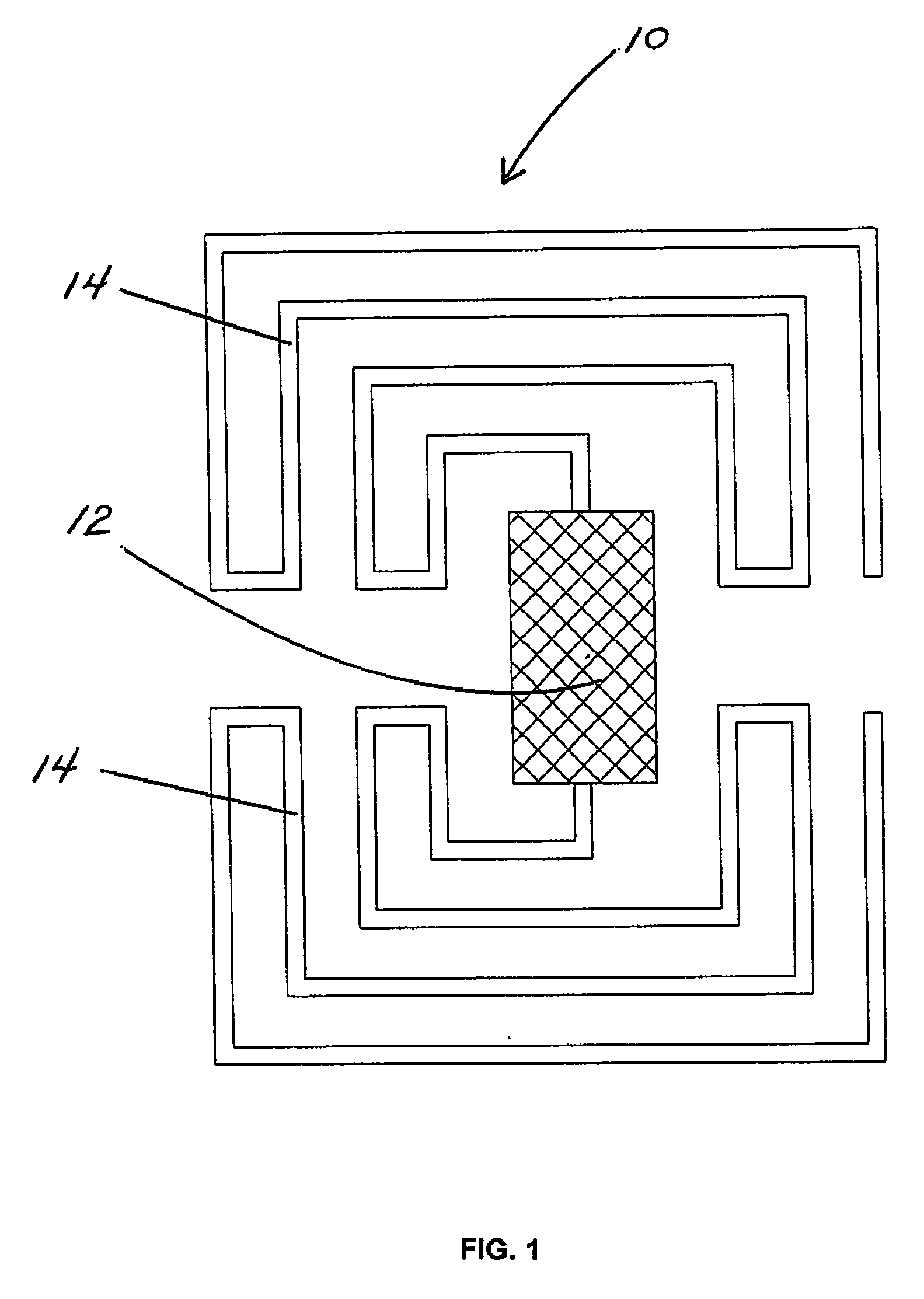
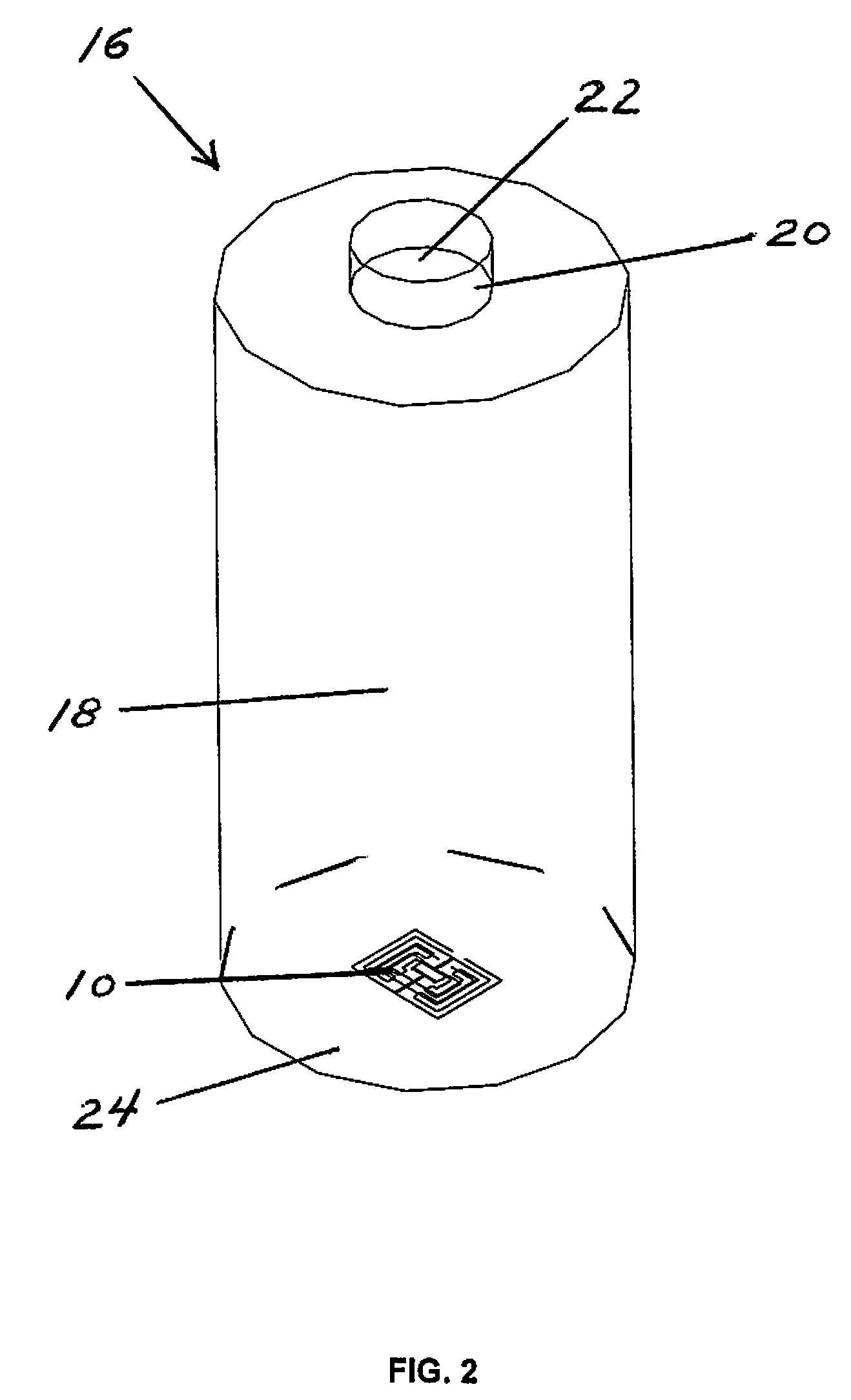
[0035]As used herein, the expression “radio frequency identification”, or RFID, is a generic term for technologies that use radio waves to automatically identify objects, such as, for example, containers for biological samples and containers for reagents for analyzing biological samples. The most common method of identification is to store a serial number that identifies the object, and perhaps other information relating to the object or contents thereof, on a microchip that is attached to an antenna. The microchip and the antenna together are called a radio frequency identification transponder or a radio frequency identification tag. The antenna enables the microchip to transmit the identification information and other information to a radio frequency identification reader. The radio frequency identification reader converts the radio waves reflected back from the radio frequency identification tag into digital information that can then be passed on to computers that can make use of...


PUM


Abstract

A method for applying a radio frequency identification tag to an object, e.g., a container, by means of an insert molding process or in-mold decorating process. Such a method can be utilized to simplify the manufacturing processes for applying a radio frequency identification tag to an object, e.g., a container. The molding process can be a conventional molding process, such as, for example, injection molding, blow molding, compression molding, transfer molding, and rotational molding. However, the conventional molding process is modified by inserting a radio frequency identification tag into the cavity of the mold prior to forming the molded article. The modified molding process results in a molded article having a radio frequency identification tag encapsulated by the polymeric material of the molded article.

Description

BACKGROUND OF THE INVENTION[0001]1. Field of the Invention[0002]This invention relates to a method for attaching a radio frequency identification tag to an article, more particularly, a container suitable for use in a diagnostic instrument.[0003]2. Discussion of the Art[0004]Currently, in the area of medical diagnostics, identification of containers is generally effected by bar code labels. Bar code labels require printing onto or application onto the surface of the container. Bar code labels require an unobstructed optical path to be read, which generates design challenges for both the container and the bar code readers. The bar code label is required to be clear, i.e., the print quality must be satisfactory and the label must be clear of foreign material, such as frost resulting from humidity and storage at low temperatures. Bar code labels generally have only a limited quantity of space, with the result that the information that can be written on a bar code label is extremely lim...

Claims


Application Information

Patent Timeline
IPC IPC(8): B32B37/02B32B37/06B32B38/10B32B37/12
CPCB29C45/14008B29L2031/712B29C45/14836B29C51/10B29C2035/047B29C2035/0822B29C2045/1404B29C2045/14049B29C2045/14237B29C2045/14254B29C2045/14844B29C2045/14852B29C2049/2412B29C2049/2466B29C2049/2472B29C2791/001B29C2791/006B29C2791/007B29C2793/00B29C2793/009B29K2023/06B29K2023/12B29K2025/00B29K2067/00B29K2105/26B29L2009/001B29C45/14221B29C2949/3094
Inventor YANG, TAHUA
Owner ABBOTT LAB INC
Why Eureka
Try Eureka