
Energy storage system

a technology of energy storage and circuits, applied in the field of energy storage systems, can solve the problems of increasing the number of devices for circuit implementation and increasing and achieve the effect of reducing the number of devices for circuit implementation and the size of printed circuit boards

Active Publication Date: 2011-12-08
HANWHA SOLUTIONS CORP
View PDF4 Cites 112 Cited by
  • Summary
  • Abstract
  • Description
  • Claims
  • Application Information

AI Technical Summary

Benefits of technology

[0008]Aspects of embodiments according to the present invention are directed toward an energy storage system including a converter (e.g., a bidirectional converter) coupled to a power generator (e.g., a renewable energy unit) and a battery in parallel, thereby reducing the number of devices for circuit implementation and the size of a printed circuit board (PCB).
[0027]An energy storage system according to embodiments of the present invention includes a converter (e.g., a bidirectional converter) coupled to a power generator (e.g., a renewable energy unit) and a battery in parallel, thereby reducing the number of devices for circuit implementation and the size of a printed circuit board (PCB). Therefore, the energy storage system according to embodiments of the present invention can substantially reduce the overall energy storage system manufacturing cost.

Problems solved by technology

As described above, the existing energy storage system requires a number of converters and an inverter, thereby increasing the number of devices for circuit implementation and increasing the size of a printed circuit board (PCB).

Method used


Image

  • Energy storage system
  • Energy storage system
  • Energy storage system

Examples


Embodiment Construction

[0036]Hereinafter, embodiments of the present invention will be described in detail with reference to the accompanying drawings.

[0037]Throughout the specification, like reference numerals refer to like elements. It will be understood that when an element is referred to as being “connected to” or “coupled to” another element, it may be directly connected to the other element, or one or more intervening elements may also be present therebetween.

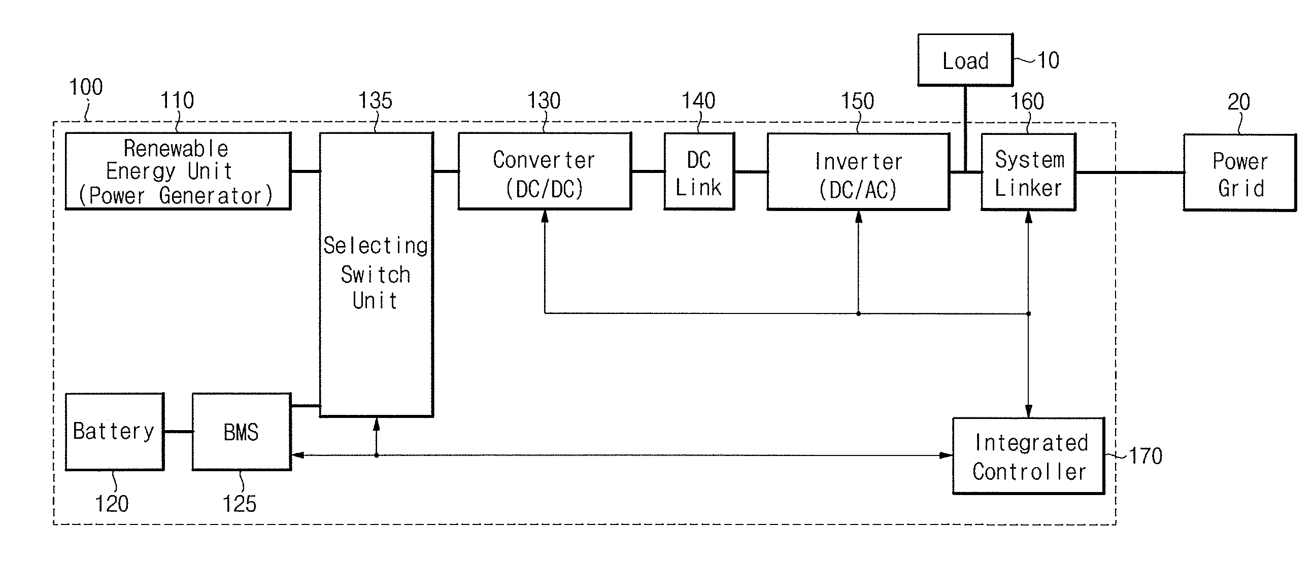
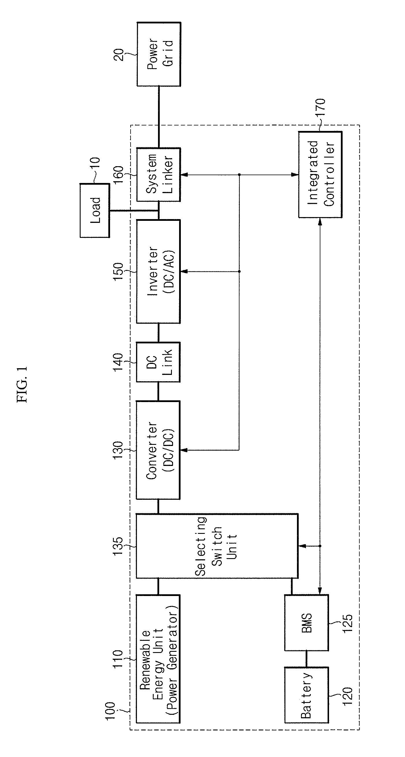
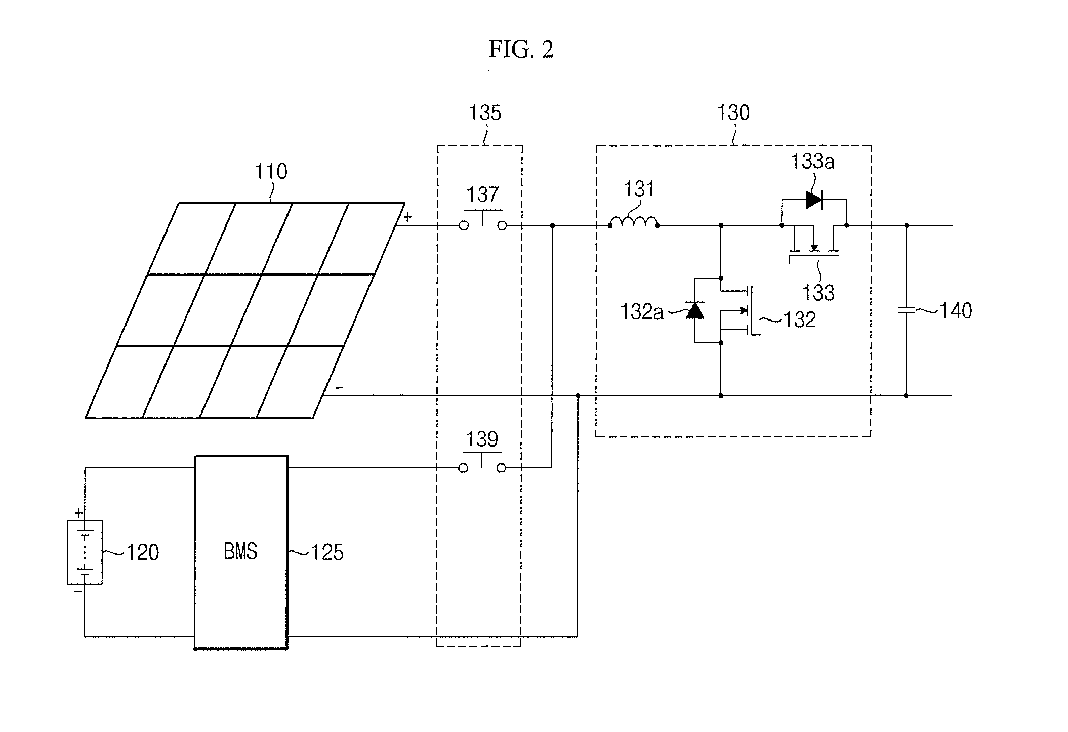
[0038]FIG. 1 illustrates a configuration of an energy storage system 100 according to an embodiment of the present invention, and FIG. 2 is a circuit diagram illustrating a power generator (e.g., a renewable energy unit), a battery, a converter (e.g., a bidirectional converter), a selecting switch unit, and a DC link illustrated in FIG. 1.

[0039]Referring to FIGS. 1 and 2, the energy storage system (ESS) 100 according to an embodiment of the present invention includes a power generator (e.g., a renewable energy unit) 110, a battery 120, a batter...


PUM


Abstract

An energy storage system includes a converter coupled between an inverter and both a power generator and a battery, thereby reducing the number of devices for circuit implementation and the size of a printed circuit board (PCB). The energy storage system is coupled to an electric power system that generates a system power, and the energy storage system includes a battery for generating a battery power and a converter coupleable to a power generator for generating an electric power and the battery in parallel, wherein the converter is configured to boost or drop a voltage of at least one of the electric power, the battery power, or the system power.

Description

CROSS-REFERENCE TO RELATED APPLICATION[0001]This application claims priority to and the benefit of Korean Patent Application No. 10-2010-0053428, filed on Jun. 7, 2010, the entire content of which is incorporated herein by reference.BACKGROUND[0002]1. Field[0003]Aspects of embodiments of the present invention relate to an energy storage system.[0004]2. Description of the Related Art[0005]In an energy storage system, a solar battery and an electric power system are linked to each other to supply power to various kinds of loads, and surplus power is stored in a secondary battery.[0006]In order to smoothly transfer power among the solar battery, the electric power system, the secondary battery and the load, the energy storage system includes a plurality of converters that convert a DC (direct current) power into another DC power of a desired level, and an inverter that inverts a DC power into an AC (alternating current) power, or an AC power into a DC power.[0007]As described above, th...

Claims


Application Information

Patent Timeline
IPC IPC(8): H02J7/00
CPCH01M10/465H02M3/1582H02J7/35Y02E60/10Y02P90/50
Inventor CHO, SUNGCHUNJUNG, NAMSUNGPARK, JUNGPILHONG, SUNGSOOROH, CHUNGWOOKHAN, SANGKYOO
Owner HANWHA SOLUTIONS CORP
Learn More