Actuator module applicable to various forms of joint

Inactive Publication Date: 2011-12-08
ROBOTIS
View PDF4 Cites 16 Cited by
  • Summary
  • Abstract
  • Description
  • Claims
  • Application Information

AI Technical Summary

Benefits of technology

[0021]Also, according to the present invention, the actuator module can compensate the insufficient torque and maintain the balance of weight due to the load balancer mounted on the actuator body or the driving axle or the rotating axle of the decelerator. Further, due to a slip ring, the actuator module may increase the durability of the wiring, make wiring arrangement easier, and make wiring without disassembling the actuator modules when assembling or disass

Problems solved by technology

But, it is difficult to make the control program of each actuator module and it becomes difficult to change the speed and torque generated from a single actuator module, because mechanical parts of each actuator module individually control the speed and torque of each joint section.
Since all joints must include more than one actuator

Method used


Image

  • Actuator module applicable to various forms of joint
  • Actuator module applicable to various forms of joint
  • Actuator module applicable to various forms of joint

Examples


first embodiment

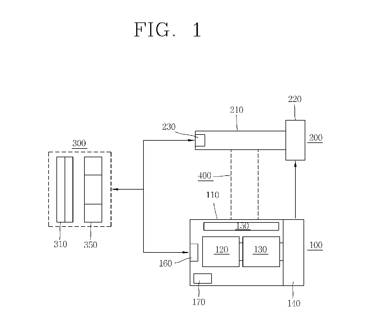
[0036]FIG. 2 illustrates an actuator module according to the present invention.

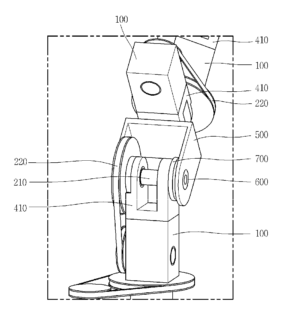
[0037]The actuator module according to the first embodiment of the present invention comprises the actuator body 100 having a driving pulley 140, a decelerator having a belt 240, a driven pulley 220 and a connecting axle 210, and a Π-shape frame 410 for forming a hinge structure that mechanically connects the actuator body 100 with the decelerator 200.

[0038]The actuator body 100 comprises a gear section 130 consisting of multiple gears that firstly decelerate the driving speed of the motor 120 (shown in FIG. 1) and interconnecting the motor 120 with the driving pulley 140. The driving pulley 140 is connected to the driven pulley 220 of the decelerator by the belt 240, and it delivers the driving power firstly decelerated from the gear section 130 of the actuator body 100 to the driven pulley 220 of the decelerator 200. The driven pulley 220 secondly decelerates the driving speed and increases the driving ...

second embodiment

[0041]FIG. 3 illustrates an actuator module according to the present invention.

[0042]The actuator module according to the second embodiment of the present invention further comprises a harmonic drive 260 in comparison to the first embodiment of the FIG. 2. The harmonic drive 260 and the driven pulley (not shown in FIG. 3) are coaxially connected to the connecting axle 210. The harmonic drive 260 generates additional torque by decelerating for the third time the driving power that was decelerated for the second time and increased in torque by the driven pulley 220. The harmonic drive 260 comprises the insert holes 270 on the outer surface for connection with external coupling elements.

[0043]As seen from above, due to the multiple decelerating means such as the driven pulley 220 and the harmonic drive 260, the adjustment of driving speed and torque becomes easier and eventually small actuator modules can be used to generate sufficient torque when large torques are needed. One of the m...

third embodiment

[0044]FIG. 4 illustrates an actuator module according to the present invention.

[0045]In FIG. 4, the driving axle of an actuator body 100 operates as a connecting axle with a decelerator which comprises a harmonic drive 260, and thus the driving power of the actuator body 100 is coaxially delivered. In addition to the harmonic drive, planetary gear, spur gear, and various other known gear structures that can be physically connected to the actuator body 100 can be provided as the decelerators. The harmonic drive 260 in FIG. 4 comprises the insert holes 270 that make connection with the external coupling elements easy.

[0046]In the above explained embodiments, the second or third decelerators such as the driven pulley or the harmonic drive may comprise an encoder 121 that detects the operating status of the decelerator such as rotation angle and feedback the detected information to the electronic circuitry 150 (i.e. control system) of the actuator body 100 for more accurate control of t...


PUM


Abstract

The present invention is about actuator modules that can be applied to various forms of joints and about joint structure using such modules, and the actuator modules includes actuator body comprising of electronics system and drive system and a separately connected decelerator, and the speed and torque obtained from the first deceleration of the actuator module body can be easily changed through the second decelerator, and since the decelerator separately connects with the actuator body it can be applied to various forms of decelerator and the actuator body can be placed varyingly making it applicable to various joint forms, and said actuator modules can be used form various joint structure.

Description

BACKGROUND OF THE INVENTION[0001]The present invention relates to a polyarticular robot and in particular to an actuator module that can be applied to various forms of joints of a polyarticular robot.[0002]A polyarticular robot is a type of robot with multiple joint sections sharing the rotation axle, and the joint sections comprise actuators that provide the driving power and various forms of coupling elements that connect the actuators. A driving power of the polyarticular robot is only provided by actuator modules and coupling elements connected directly to the driving axle of actuator modules.[0003]But, it is difficult to make the control program of each actuator module and it becomes difficult to change the speed and torque generated from a single actuator module, because mechanical parts of each actuator module individually control the speed and torque of each joint section. Since all joints must include more than one actuator modules, it is not easy to form various forms of j...

Claims


Application Information

Patent Timeline
IPC IPC(8): H02K7/00
CPCB25J9/08B25J17/0258B25J17/0241B25J9/126
Inventor KIM, BYOUNG SOOJANG, WOOK
Owner ROBOTIS
Why Eureka
Try Eureka