Hand-held pointing device, software cursor control system and method for controlling a movement of a software cursor

a software cursor and control system technology, applied in the direction of instruments, electric digital data processing, cathode-ray tube indicators, etc., can solve the problems of linear movement remaining unconsidered, the handling of these systems is difficult, and the computation effort for determining the control signal for controlling the movement of the software cursor is significantly reduced, and the control accuracy and ease of use may be significantly improved. , the effect of accurate determination of the control signal

Inactive Publication Date: 2011-12-08
FRAUNHOFER GESELLSCHAFT ZUR FOERDERUNG DER ANGEWANDTEN FORSCHUNG EV
View PDF2 Cites 16 Cited by
  • Summary
  • Abstract
  • Description
  • Claims
  • Application Information

AI Technical Summary

Benefits of technology

[0018]Embodiments according to the present invention are based on the central idea that the movement of a software cursor may be controlled by a hand-held pointing device being able to capture sensor data and image data. By using this combination of captured data, the computational effort for determining a control signal for controlling the movement of the software cursor may be significantly reduced, since the usage of a low-complexity image processing method for extracting the necessitated control data from the recorded images may be sufficient, in comparison with known image based software cursor control systems working in the visible spectral range. In comparison to infrared based software cursor control systems, the inventive concept does not necessitate markers. Further, in comparison to known sensor based software cursor control systems, the control accuracy and the ease of use may be significantly improved by using the inventive concept, since using additional image information may allow a more accurate determination of the control signal especially for steady linear movement.

Problems solved by technology

The above input devices only offer limited interaction possibilities in the case of a great expanse of the projection area, such as in the case of a beamer presentation, or in the case of several projection areas distributed in space, such as in a control room and / or operation center.
Due to the sensor principle, only accelerated linear movements and rotational movements, but no steady linear movements can be detected directly, which is why the handling of these systems may be difficult, particularly with respect to the exact positioning of the software cursor.
Due to this principle, however, only the rotational position of the pointing device and the changes thereof can be detected with this, whereas linear movements also remaining unconsidered here.
These systems necessitate the installation of a camera arrangement in space as well as the calibration of this arrangement at least with respect to the respective spatial geometry, and hence a great installation effort.
Furthermore, such systems necessitate special, usually intensive image evaluation methods, and hence computer components with high computation power.
In these example systems, there is also a basic disadvantage with respect to general applicability in that a camera arrangement has to be installed in space.
Furthermore, it is a limitation of the application of such a pointing system that the light falling onto the projection area needs to be reflected sufficiently therefrom, and hence the applicability of the pointing system depends directly on the optical properties of the projection area.
For example, the light emitted by a laser pointer is not reflected sufficiently by an LCD screen.
What is generally disadvantageous for the general employment of such a pointing system is the installation of optical markers, particularly components emitting infrared light, at designated locations in space in a predefined configuration.
Disadvantages of this system concept consist in the fact that intensive image evaluation methods, which necessitate a relatively high computation effort, and hence powerful computer components, have to be employed for the robust recognition and measurement of the optical marker representing the cursor, in terms of reliable determination of the spatial orientation of the marker.
Furthermore, it can be seen as a disadvantage that meanwhile generally used well-known forms of the cursor, which characterize forms of interaction determined depending on the context, are replaced by cursor forms unknown to the user and allowing for automatic detection of the cursor, and the interaction is made difficult thereby.
Moreover, with respect to the robust automatic recognition capability and measurability, the size of the optical marker has to be changed depending on the distance of the projection area, which poses the risk of potentially obscuring substantial image structures, such as parts of a graphical user interface, by the marker structure, and hence complicating interaction.
The basic difficulty in such a system concept is to form the optical markers so that they are not perceived as disturbing by the viewer, but can still be detected automatically.
According to the current state of research, this can only be achieved when utilizing light in a spectral range in which the human eye is insensitive, for example in the infrared range.

Method used


Image

  • Hand-held pointing device, software cursor control system and method for controlling a movement of a software cursor
  • Hand-held pointing device, software cursor control system and method for controlling a movement of a software cursor
  • Hand-held pointing device, software cursor control system and method for controlling a movement of a software cursor

Examples


Embodiment Construction

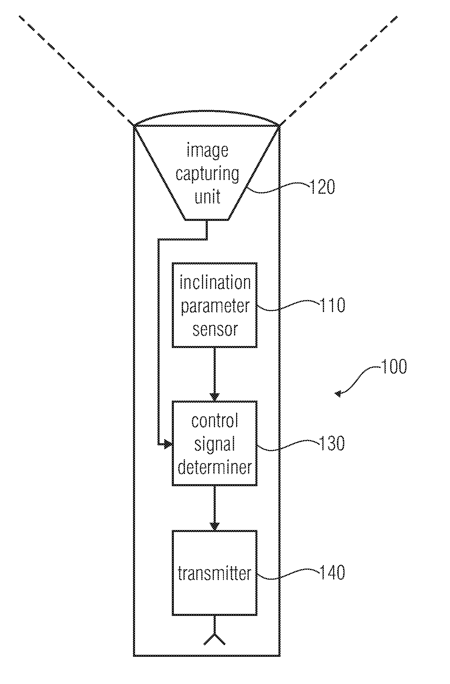
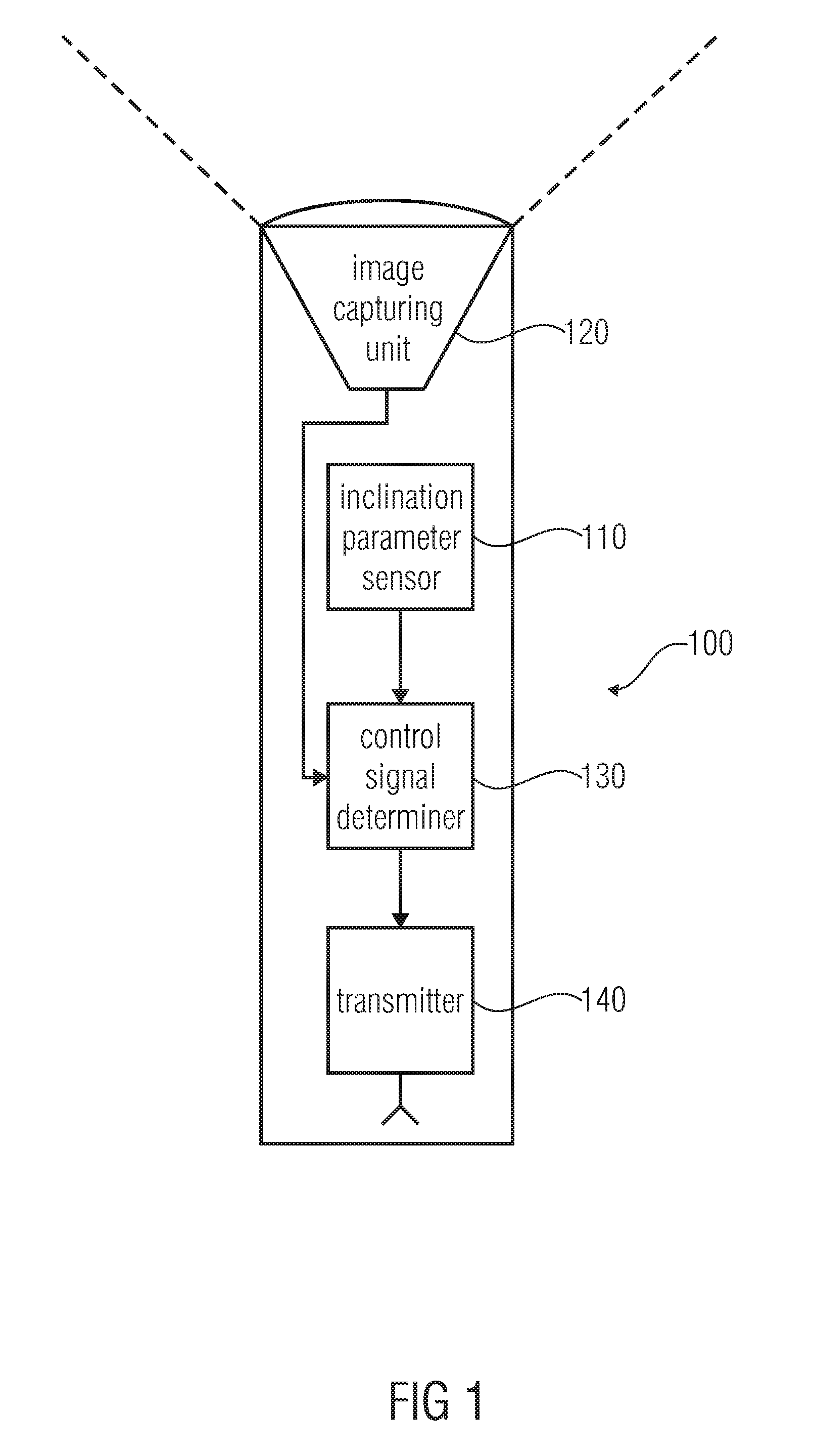
[0026]FIG. 1 shows a block diagram of a hand-held (or portable) pointing device 100 for controlling a movement of software cursor according to an embodiment of the invention. The hand-held pointing device 100 comprises an inclination parameter sensor 110 and an image capturing unit 120, wherein the inclination parameter sensor 110 determines an inclination parameter. The movement of the software cursor in a vertical direction is controllable based on the inclination parameter. Further, the image capturing unit 120 records images within the visible spectral range, wherein the movement of the software cursor in a horizontal direction is controllable based on the recorded images.

[0027]The inclination parameter may indicate, for example, an intensity of an acceleration of the hand-held pointing device and a direction of the acceleration. Since the inclination parameter sensor 110 is effected by the gravitational field all the time, an angle between the gravitational field and a pointing...


PUM


Abstract

A hand-held pointing device for controlling a movement of a software cursor comprises an acceleration detector and an image capturing unit. The acceleration detector determines an inclination parameter, wherein the movement of the software cursor in a vertical direction is controllable based on the inclination parameter. Further, the image capturing unit records images within the visible spectral range, wherein the movement of the software cursor in a horizontal direction is controllable based on the recorded images.

Description

CROSS-REFERENCE TO RELATED APPLICATIONS[0001]This application claims priority from European Patent Application No. 10164768.3, which was filed on Jun. 2, 2010, and is incorporated herein in its entirety by reference.BACKGROUND OF THE INVENTION[0002]Embodiments according to the invention relate to technical systems for controlling a software cursor and particularly a hand-held pointing device for controlling a movement of a software cursor, a software cursor control system for controlling a movement of a software cursor and a method for controlling a movement of a software cursor.[0003]For interacting with the graphical user interface of a computer program, in general, classic input devices, such as computer mice, mechanical or optical, or input devices having touch-sensitive areas, so-called touchpads, are employed. These allow for reliable and intuitive interaction with the graphical user interface when the screens and / or projection areas are in immediate proximity of the user. The...

Claims


Application Information

Patent Timeline
Patent Type & Authority Applications(United States)
IPC IPC(8): G06F3/038G06F3/033G06F3/0346
CPCG06F3/0346G06F3/0317
Inventor RUCKHAEBERLE, MARTINSCHUETZ, CHRISTIANGEISLER, JUERGEN
Owner FRAUNHOFER GESELLSCHAFT ZUR FOERDERUNG DER ANGEWANDTEN FORSCHUNG EV
Why Eureka
Try Eureka