
Sample analyzing apparatus

a technology of sample analysis and sample, applied in the direction of optical radiation measurement, instruments, spectrometry/spectrophotometry/monochromators, etc., can solve the problems of take time to calculate the concentration, and become difficult to measure the concentration with high accuracy, so as to reduce a number of components and high accuracy

Inactive Publication Date: 2011-12-08
HORIBA LTD
View PDF2 Cites 7 Cited by
  • Summary
  • Abstract
  • Description
  • Claims
  • Application Information

AI Technical Summary

Benefits of technology

[0018]In accordance with this invention having the above-mentioned arrangement, it is possible to reduce a number of the components as much as possible and to measure an absorption spectrum in more than two wavelength regions whose absorption rate (transmission rate) differs from each other by a cell length appropriate for each wavelength region so as to obtain the measurement result with high accuracy.

Problems solved by technology

This is because a light amount of the transmitted light becomes too small for a case of more than or equal to the absorbance 2 so that it becomes difficult to measure the concentration with high accuracy due to an influence of the noise of a measurement system.
Meanwhile, in case of less than or equal to the light absorbance 1, a change of the light absorption due to a change of a concentration of a contained component becomes too small so that it becomes difficult to measure the concentration with high accuracy.
However, with this method, since it takes time to switch the sample cell, there is a problem that it takes time to calculate the concentration.
However, with this arrangement, a number of the components is increased, resulting in a problem that the cost is increased.
However, this arrangement never considers a relationship between the optical path length and the wavelength of the irradiated light, and it is nothing more than just enlarging the measurable range of the wavelength with securing a desired wavelength resolution.

Method used


Image

  • Sample analyzing apparatus
  • Sample analyzing apparatus
  • Sample analyzing apparatus

Examples


Embodiment Construction

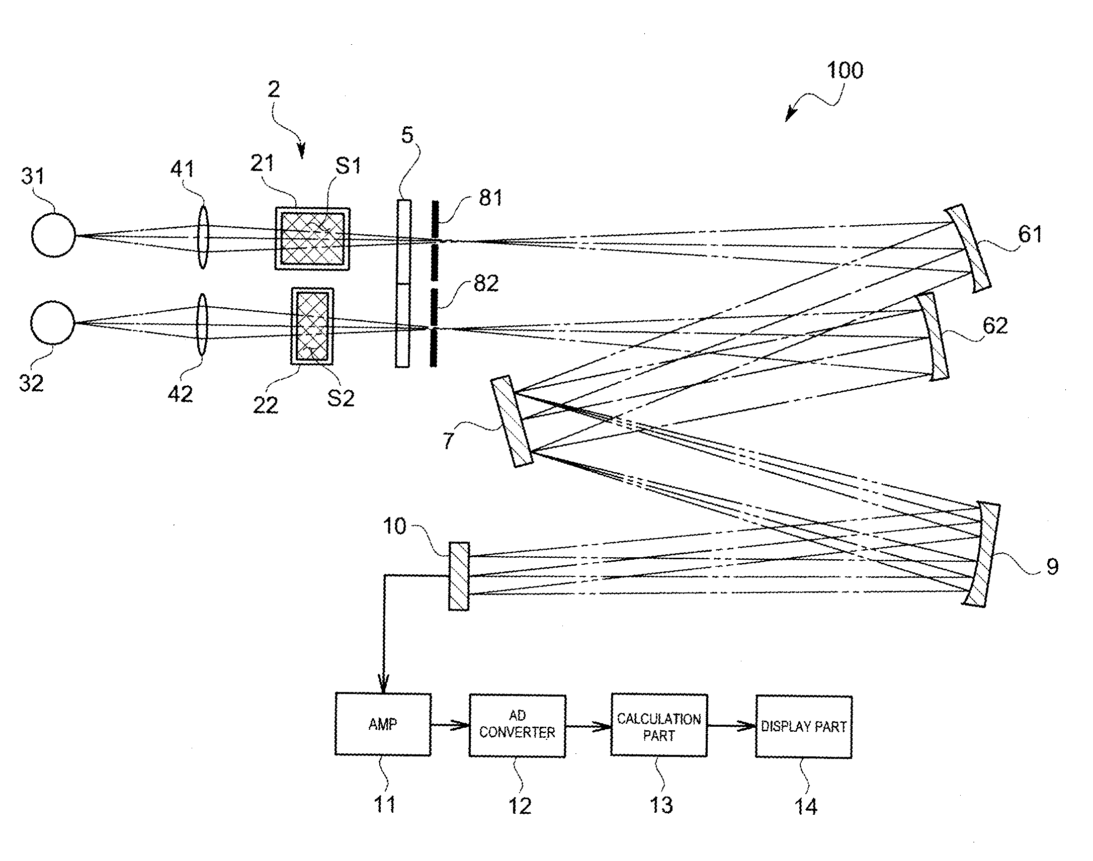
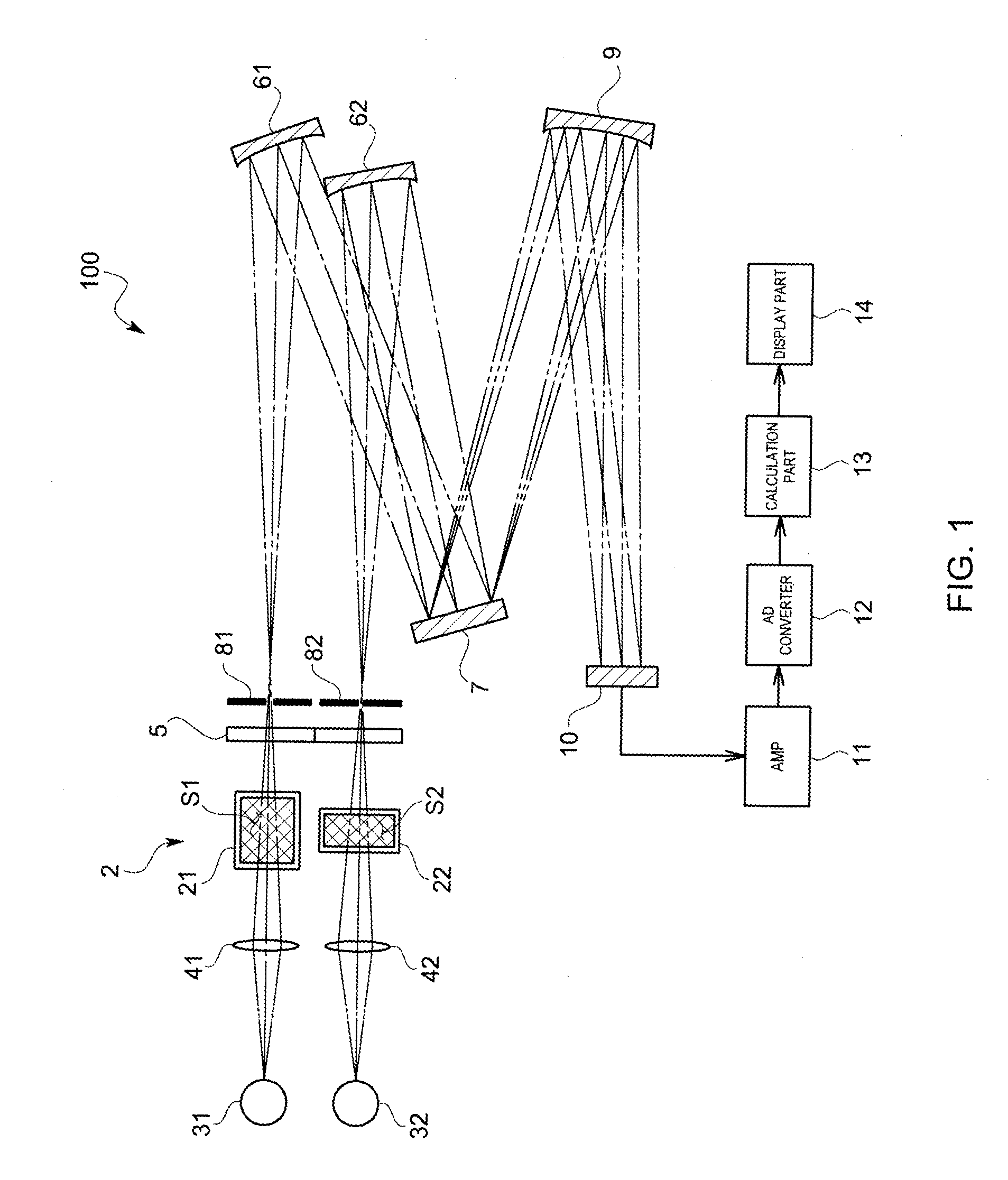
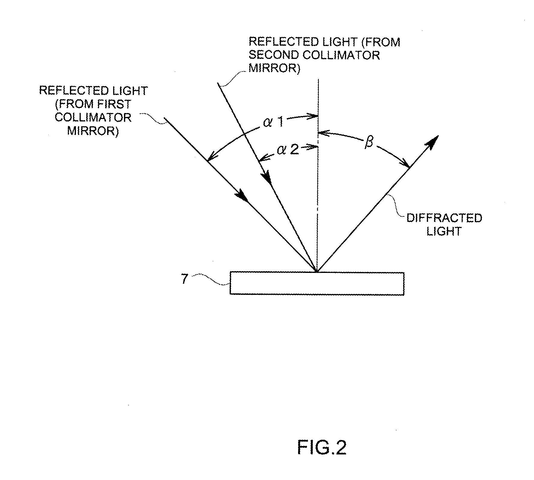
[0036]A sample analyzing apparatus 100 in accordance with this invention will be explained with reference to drawings. FIG. 1 is a configuration diagram schematically showing the sample analyzing apparatus 100 in accordance with this embodiment, and FIG. 2 is a schematic view showing incidence angles α1, α2 of a reflected light to a diffraction grating 7, and a diffraction angle β.

[0037]The sample analyzing apparatus 100 in accordance with this invention comprises, as shown in FIG. 1, a sample cell part 2 that houses a sample, a first light source 31 and a second light source 32 that irradiate the light in a predetermined wavelength region on the sample cell part 2, a first collimator mirror 61 and a second collimator mirror 62 that collimate the transmitted light passing the sample cell part 2, a diffraction grating 7 that disperses the reflected light collimated by the first and the second collimator mirrors 61, 62, a light collecting mirror 9 that condenses the diffracted light d...


PUM


Abstract

Provided is a sample analyzing apparatus by which highly accurate measurement results can be obtained. The sample analyzing apparatus is provided with: a sample cell part constituting a plurality of cell spaces; light source parts that irradiate light in wavelength regions different from each other on the cell spaces; a plurality of collimator mirrors that are arranged to correspond to the cell spaces respectively and that collimate the transmitted light that has passed through the cell spaces; a diffraction grating that disperses the reflection light collimated by the collimator mirrors; a light collecting mirror that collects the light dispersed by means of the diffraction grating; and a light detector that detects the light collected by the light collecting mirror.

Description

FIELD OF THE ART[0001]This invention relates to a sample analyzing apparatus that analyzes a component concentration in a sample by the use of the absorption spectrum obtained by irradiating the light on the sample and dispersing the transmitted light passing the sample.BACKGROUND ART[0002]As this kind of the sample analyzing apparatus, as shown in the patent document 1, there is a sample analyzing apparatus that collects the light from a light source such as, for example, a halogen lamp, by a light condensing lens, irradiates the collected light on a sample cell, disperses the transmitted light passing the sample cell by the use of a diffraction grating, and then detects and calculates an absorption spectrum by a multichannel detector so as to analyze a component concentration of the sample.[0003]In case of measuring the light absorption of the sample by the use of the sample analyzing apparatus, the absorbance 1 (transmittance 10%) through the absorbance 2 (transmittance 1%) is mo...

Claims


Application Information

Patent Timeline
IPC IPC(8): G01N21/59
CPCG01J3/02G01J3/0208G01N2021/0357G01J3/42G01N21/31G01J3/1804G01N21/27G01J3/18
Inventor YOKOYAMA, ISSEI
Owner HORIBA LTD
Learn More